Download
1 / 89
890 likes | 985 Views
Design of PM helicon arrays. Optimization of the discharge tube Design of the permanent magnets Design of a multi-tube array Design and construction of a test chamber Antennas and the RF distribution system Experimental results Design of a compact module

E N D
Design of PM helicon arrays • Optimization of the discharge tube • Design of the permanent magnets • Design of a multi-tube array • Design and construction of a test chamber • Antennas and the RF distribution system • Experimental results • Design of a compact module • Ideas for further improvements to be tested UCLA
A commercial helicon etcher (PMT MØRI) It required two heavy electromagnets with opposite currents.
Previous experiment with 7 tubes The “stubby” tube It required a large electromagnet UCLA
Plasmas merged; density is uniform High density and uniformity were achieved UCLA
Optimization of discharge tube: HELIC code Radial profiles are arbitrary, but B and n must be uniform axially. HELIC gives not only the wave fields but also R, the loading resistance. D. Arnush, Phys. Plasmas 7, 3042 (2000). UCLA
The Low-field Peak UCLA
Mechanism of the Low Field Peak Basic helicon relations UCLA
The peak depends on the type of antenna Single loop: m = 0, bidirectional HH (half-wavelength helical): m = 1, undirectional Nagoya Type III: m = 1, bidirectional
Typical scan of Rp vs n, B Each point requires solving a 4th order differential equation >100 times. A typical scan takes ~ 3 hours on a PC. UCLA
Matrices for optimizing discharge tube Vary the tube length and diameter Vary the RF frequency Vary the endplate conductivity UCLA Vary the pressure and frequency
Vary the frequency UCLA
Vary the endplate material Initially, it seems that the conducting endplate is better. However, it is because the phase reversal at the endplate has changed, and the tube length has to be ~1/4 wavelength longer to get constructive interference. By changing H, almost the same R can be achieved. UCLA
Relation of R to plasma density Rp << Rc UCLA
Relation of R to plasma density Rp > Rc UCLA
Final design UCLA
Design of PM helicon arrays • Optimization of the discharge tube • Design of the permanent magnets • Design of a multi-tube array • Design and construction of a test chamber • Antennas and the RF distribution system • Experimental results • Design of a compact module • Ideas for further improvements to be tested UCLA
Internal field External field Characteristics of permanent magnet rings UCLA
The B-field of annular PMs The field reverses at a stagnation point very close to the magnet. Plasma created inside the rings follows the field lines and cannot be ejected. UCLA
Optimization of magnet geometry actual Result: Field strength magnet volume Spacing improves uniformity slightly actual UCLA
The field of 4 stacked magnet rings The internal and external fields at various radii. The individual rings can be seen at large radii. Calibration of the calculated field with a gaussmeter. UCLA
External field Internal field Proof of principle on 3” diam tube UCLA
Radial density profiles at Z1 and Z2 Upper probe x 1010cm-3 Lower probe Proof of principle: discharge in the external field gives much more plasma downstream. UCLA
The final design for 2” tubes Material: NdFeB Bmax = 12 kG Attractive force between two magnets 2 cm apart: 516 Newtons = 53 kg The magnets are dangerous! UCLA
Single tube, final configuration Radial Bz profiles at various distances below the magnet. Discharge tube UCLA
Design of PM helicon arrays • Optimization of the discharge tube • Design of the permanent magnets • Design of a multi-tube array • Design and construction of a test chamber • Antennas and the RF distribution system • Experimental results • Design of a compact module • Ideas for further improvements to be tested UCLA
Design of array Radial density profiles at Z1 = 7.4 cm and Z2 = 17.6 cm below discharge. The density at Z2 is summed over nearest tubes. UCLA
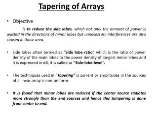
Computed uniformity n(x) for various y Half-way between rows 1/4-way between rows Directly under a row Beyond both rows
A tube spacing of 7” is chosen For a single row, a distance L = 17.5 cm between two tubes gives less than 2% ripple in density. UCLA
Design of PM helicon arrays • Optimization of the discharge tube • Design of the permanent magnets • Design of a multi-tube array • Design and construction of a test chamber • Antennas and the RF distribution system • Experimental results • Design of a compact module • Ideas for further improvements to be tested UCLA
An 8-tube linear test array Top view UCLA
Possible applications • Web coaters • Flat panel displays • Solar cells • Optical coatings A web coater UCLA
The array source is vertically compact Side view Probe ports The magnets can be made in two pieces so that they hold each other on an aluminum sheet. Once placed, the magnets cannot easily be moved, so for testing we use a wooden support. UCLA
Water and RF connections These will be shown in detail later UCLA
Design of PM helicon arrays • Optimization of the discharge tube • Design of the permanent magnets • Design of a multi-tube array • Design and construction of a test chamber • Antennas and the RF distribution system • Experimental results • Design of a compact module • Ideas for further improvements to be tested UCLA
Antennas The antennas are m = 0 loops made of three turns of 1/8” diam copper tubing. The reason for m = 0 is that m = 1 antennas are too long, and much of the plasma is lost by radial diffusion before exiting the tube. The antenna must be close to the exit aperture and be tightly wound onto the tube. The helicon wave pattern for m = 0 is a peculiar one but theory is straightforward. The wave changes from pure electromagnetic to pure electrostatic in each half cycle. UCLA
The RF system The critical elements are the junction box and the transmission lines. UCLA