Download
1 / 41
440 likes | 663 Views
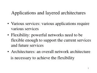
Applications and Layered Architecture. Layering. Layering : the grouping of the communication functions into related and manageable sets Network architecture : a set of protocols that specify how every layer is to function Benefits of layering: Simplifying he design process

E N D
Layering • Layering: the grouping of the communication functions into related and manageable sets • Network architecture: a set of protocols that specify how every layer is to function • Benefits of layering: • Simplifying he design process • Leading to flexibility in modifying and developing the network
Applications and Layered Architecture Examples of Layering
Examples of Layering • All these examples involve a client/server relationship. • A server process waits for incoming requests by listening to a port. • Client processes make requests as required. • The server process usually runs in the background and is referred to as a daemon. • Ex. httpd refers to the server daemon for HTTP.
HTTP client sends message requesting document. HTTP daemon listening on TCP port 80 interprets message HTTP daemon sends a result code and a description of the information that the client will receive HTTP daemon sends the requested file through the TCP port. HTTP daemon disconnects the connection. Text is displayed by client browser, which interprets the HTML format. GET/INFOCOM/INDEX.HTML HTTP/1.0 HTTP/1.1 200 OK Server: Apache/1.2.5 FrontPage 3.0.4 Content-Length 414 Content-Type: text/html <html> <head> <title> IEEE Infocom ‘99 Web Browsing
Request HTTP server HTTP client Response HTTP client/server Interaction
HTTP server HTTP client Ephemeral Port # Port 80 GET 80, # TCP TCP #, 80 STATUS TCP Pipe
Application requests name to address translation. Resolver composes query message. Resolver sends UDP datagram encapsulating the query message. DNS server looks up address and prepares response. DNS sends UDP datagram encapsulating the response message. Header: OPCODE=SQUERY Question: QNAME = tesla.comm.toronto.edu., QCLASS=IN, QTYPE=A Header: OPCODE=SQUERY, RESPONSE, AA Question: QNAME= tesla.comm.toronto.edu., QCLASS=IN, QTYPE=A Answer: tesla.comm.toronto.edu. 86400 IN A 128.100.11.26 DNS Query
The mail application establishes a TCP connection (port 25) to its local SMTP server. SMTP daemon issues message to the client, indicating that it is ready to receive mail. Client sends a HELO message and identifies itself. SMTP daemon issues a 250 message, indicating the client may proceed. 220 tesla.comm.toronto.edu ESMTP Sendmail 8.9.0/8.9.0; Thu, 2 Jul 1998 05:07:59 –0400 (EDT) HELO bhaskara.comm.utoronto.ca 250 tesla.comm.toronto.edu Hello bhaskara.comm [128.100.10.9], pleased to meet you SMTP and E-mail (1/3)
Client sends sender’s address. If successful, SMTP daemon replies with a 250 message. Client sends recipient’s address. A 250 message is returned. Client sends a DATA messages requesting permission to send the mail message. MAIL FROM: <banerjea@comm.utoronto.ca> 250 <banerjea@comm.utoronto.ca> … Sender ok RCPT TO: <alg@nal.utoronto.ca> 250 <alg@nal.utoronto.ca> … Recipient ok DATA SMTP and E-mailm (2/3)
The daemon sends a message giving the client permission to send. Client sends the actual text. Daemon indicates that the message is accepted for delivery. A message ID is returned. Client indicates that the mail session is over. Daemon confirms the end of the session. 354 Enter mail, end with ’’.’’ on a line by itself Hi Al, This section needs a lot of work…. 250 FAA00803 Message accepted for delivery QUIT 221 tesla.comm.toronto.edu closing connection SMTP and E-mail (3/3)
Applications and Layered Architecture The OSI Reference Model
The OSI reference model • There was pressure in the 1970s for an open systems architecture. • International Organization for Standardization (ISO) developed a reference model for open system interconnect (OSI) and later to develop associated standard protocols. • The OSI reference model provided a framework for the overall communications process and was intended to facilitate the development of standards.
The OSI reference model • The OSI model partitions the overall communication process into functions that are carried out by various layers. • In each layer a process on one machine carries out a conversation with a peer process on the other machine. • The processes at layer n are referred to as layer n entities.
The OSI reference model • Layer n entities communicate by exchanging protocol data units (PDUs). • Each PDU contains a header and usually user information in the form of a service data unit (SDU). • The behavior of the layer n entities is governed by a set of rules , called the layer n protocol.
The OSI reference model • The layer n+1 entities make use of the services provided by layer n. • Layer n+1 passes a block of information to layer n through a software port called the layer n service access point (SAP). • This block of information consists of control information and a layer n SDU , which is the layer n+1 PDU. • The layer n entity uses the control information to form the header of the layer n PDU.
Encapsulation • Layer n SDU is encapsulated in the layer n PDU. • In principle, the layer n protocol does not interpret or make use of the information contained in the SDU. • Layer n+1 is only interested in the correct execution of the service, not the details of the implementation of the layer below.
n-PDUs n entity n entity Peer-to-Peer Communication
Layer Services n+1 entity n+1 entity n-SDU n-SDU n-SAP n-SAP n-SDU H n entity n entity n-SDU H n-PDU
Connection-oriented service • Three phases: • Establishing a connection between two layer n SAPs. • Negotiating connection parameters • Initializing “state information” • Transferring n-SDUs using the layer n protocol. • Tearing down the connection and releasing the various resources allocated to the connection
Connectionless service • Connectionless service does not require a connection setup, and each SDU is transmitted directly from SAP to SAP. • The control information from layer n+1 to layer n must contain the complete address information required to transfer the SDU.
Confirmed/Unconfirmed • Confirmed service: the sender is eventually informed of the transmission outcome. • Connection setup is usually a confirmed service. • A connectionless service can be confirmed or unconfirmed.
Segmentation Reassembly n-SDU n-SDU n-PDU n-PDU n-PDU n-PDU n-PDU n-PDU Segmentation/Reassembly
Blocking Unblocking n-SDU n-SDU n-SDU n-SDU n-SDU n-SDU n-PDU n-PDU Blocking/Unblocking
The Seven-layer Model Application A Application B Application Layer Application Layer Presentation Layer Presentation Layer Session Layer Session Layer Transport Layer Transport Layer Communication Network Network Layer Network Layer Network Layer Network Layer Data Link Layer Data Link Layer Data Link Layer Data Link Layer Physical Layer Physical Layer Physical Layer Physical Layer Electrical and/or Optical Signals
The Seven Layers • The application layer provides services that are frequently required by applications that involve communications. • The presentation layer provides the application layer with independence from differences in the representation of data. • The section layer provides dialogue control and session synchronization. • The transport layer is responsible for the end-to-end transfer of message from a session entity in the source host to a session entity in the destination entity.
The Seven Layers • The network layer provides for the transfer of data across the communication network. • The data link layer provides for the transfer of data across a transmission link that directly connects two nodes. • This includes the case where multiple nodes are connected to broadcast medium (LAN). • The physical layer deals with the transfer of bits over a communication channel.
Rrouting • Routing: the procedure that is used to select a path across the network. • Routing is the key aspect of the network layer. • This function makes the network layer the most complex layer in the reference model.
A Packet-switching Network C PS = packet switch C = computer PS C PS PS PS C C C A single routing procedure is used.
G = gateway/router net 3 G net 1 G G G G net 5 net 2 net 4 G An internetwork
Internet sublayer • The internet sublayer are required to route the data between gateways. • The internet sublayer must deal with the differences among the component networks. • Addressing • Packet size
data Application Layer Application Layer ah data Presentation Layer Presentation Layer ph data Session Layer Session Layer sh data Transport Layer Transport Layer th data Network Layer Network Layer data nh Data Link Layer Data Link Layer dt dh data Physical Layer Physical Layer bits Header and Trailer Application A Application B
Applications and Layered Architecture Overview of TCP/IP Architecture
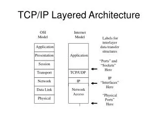
Application Layer Application Layer Transport Layer Transport Layer Internet Layer Internet Layer Network Interface Network Interface (b) (a) TCP/IP network architecture
TCP/IP Architecture • The TCP/IP architecture consists of four layers. • TCP/IP model does not require strict layering. • The application layer may bypass intermediate layers. • Two basic types of services in the transport layer: • TCP (Transmission Control Protocol) : reliable connection-oriented transfer • UDP (User Datagram Protocol): best-effort connectionless transfer • The internet layer provides a single service: best-effort connectionless packet transfer • The network interface layer deals with the network-specific aspects of the transfer of packets.
Machine B Machine A Application Application Transport Transport Router/Gateway Internet Internet Internet Network Interface Network Interface Network Interface Network 1 Network 2 The internet layer and network interface layers
IP Network Interface 3 Network Interface 2 Network Interface 1 TCP/IP protocol graph HTTP RTP SMTP DNS TCP UDP
An example of an internet (2,1) (1,1) (2,2) router s PPP (1,3) r w Ethernet (1,2) Server PC HTTP HTTP TCP Router TCP IP IP IP Net Interface Net Interface Net Interface Ethernet PPP
IP datagram in an Ethernet frame IP Header Header contains source and destination physical addresses; network protocol type Frame Check Sequence Ethernet Header
HTTP Request Encapsulation of PDUs in TCP/IP Header contains source and destination port numbers TCP Header Header contains source and destination IP addresses; transport protocol type IP Header Header contains source and destination physical addresses; network protocol type Frame Check Sequence Ethernet Header