Download
1 / 35
360 likes | 548 Views
Seismic source inversion in mining environments Simone Cesca Institute of Geophysics, University of Hamburg simone.cesca@zmaw.de http://mine.zmaw.de. Outline The MINE project background, structure and project aims Seismic source inversion problem theory and methods

E N D
Seismic source inversion in mining environments Simone Cesca Institute of Geophysics, University of Hamburg simone.cesca@zmaw.de http://mine.zmaw.de
Outline The MINE project • background, structure and project aims Seismic source inversion problem • theory and methods • point and kinematic source inversion using the Kiwi tools Source inversion in mining environments • an application to coal mining induced seismicity (Ruhr, Germany)
The MINE project, a quick overview MINing Environment: continuous monitoring and simultaneous inversion Funding, positions, timeline • German Ministery of Education and Science (BMBF – Geotechnologien Programme) • Junior Research project, 1 Leading Scientist + 3 PhDs • 3+3 years duration (started 1.7.2010) Aims • Mining monitoring (seismicity, fracturing, stress perturbation) and imaging • Adapt full waveform techniques from classical seismology and to mining • Combine information from different data streams • Provide portable software tools to analyse mine datasets
WP1 Detection, Location, Characterization WP2 Source Inversion WP3 Stress inversion WP4 Tomography Research lines Detection and location using full waveforms Signal characterization Moment tensor inversion Extended source parameters Spatio-temporal patterns of seismicity Stress inversion (seismicity patterns and focal mechanisms) Local earthquake tomography
Hamm, Ruhr region Biscoff et al. (2010) Courtesy M. Bischoff
Pyhäsalmi Deep metal mine in Europe Collaboration with NORSAR (Kuhn, Oye, Roth, Nath) 3D velocity model Multi-stream monitoring system Seismic Internal deformation Thermal measurements Others Figure T. Mäki (2000)
Cerville 50 m 125 m LIMESTONE (DOLOMIE) MARLS 190 m SALT Courtesy P. Jousset
Source inversion in seismology, overview Global CMT catalogue, shallow earthquakes, 1976-2005 Source: http://cgsweb.moeacgs.gov.tw/ Slip map kinematic model (Li et al. 2002)
Source inversion in seismology, what do we need? Data access (waveform and metadata) Data preprocessing Green's functions (database) Inversion method, Inv. Parameters (e.g. BP, tapers, ...) Moment tensor / Kinematic source Inversion routine Plotting and result evaluation
Source inversion in seismology using the Kiwi tools OpenSource Running under Linux Python + Fortran implementation http://kinherd.org
Point source model, double couple & moment tensor Earthquakes is often well modeled in terms of shear cracks, using a point source representation (DC model). More complete point source model is represented by a moment tensor (MT) MT = MTDC + MTCLVD + MTISO after Hasegawa et al. (1989)
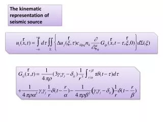
Extended source model, definitions Extended sources may be reproduced by superposition of several point sources distributed along a planar (or bended) rupture surface. Each point source start radiating when reached by the rupture front. Radiation lasts for a given (rise) time.
The eikonal source model Circular area, plus constraints Rupture velocity scales with shear velocity Despite its flexibility, the eikonal source model is described by only 13 parameters (considering constraints and earth model as fixed and known)
Source model parameters (13) Time Lat Lon Depth M0 Strike Dip Rake Rad NucX NucY RuptV RiseT General source description Source location Radiation pattern Rupture process Scale of source model Point source Finite source Information from data Low frequencies High frequencies Inversion priority Step 1, 2 Step 3 Source model parameters and inversion priorities
Greece, Shallow earthquakes 2003-2007 extended sources Cesca et al. JGR 2010
Source inversion, natural and induced seismicity Cesca et al. submitted
Ruhr region • Coal mining induced seismicity monitored by Ruhr University since 1983 • About 1000 events are recorded between 0.7<ML<3.3 every year • Hamm region (blue circle) • >7000 events in 2006-2007 (14 months) • 913 events 0.0<ML<2.0 • DC inversion • MT inversion • Kinematic inversion and rupture modeling Bischoff et al. 2010
Seismicity follows longwall mining, Epicenters are spreaded over an area of about 2x2km 6 broadband stations (5 Guralp CMG, pink; 1 Trillium 40, purple) 9 short-period (Mark L-4C-3D, orange) 3 subsurface stations (yellow) We work here at 0.5-2Hz or 1-4Hz, only BB stations are used
Seismicity follows longwall mining Additional clusters Average depth above mining level Bimodal frequency-magnitude distribution
1 Step 1, Focal mechanism (DC and full moment tensor) amplitude spectra inversion, whole waveform Depth M0 Strike Dip Rake Depth M0 Strike Dip Rake Time Lat Lon Inversion strategy Time Time Lat Lat Lon Lon Depth M0 Strike Dip Rake Rad NucX NucY RuptV RiseT Depth M0 Time Lat Lon Depth M0 Strike Dip Rake Rad NucX NucY RuptV RiseT Time Lat Lon Rad NucX NucY RuptV RiseT Time Lat Lon Depth M0 Strike Dip Rake Rad NucX NucY RuptV RiseT
1 Step 1, Focal mechanism (DC and full moment tensor) amplitude spectra inversion, whole waveform Depth M0 Strike Dip Rake 2 Step 2, Polarity control / Centroid location time domain inversion, whole waveforms Depth M0 Strike Dip Rake Time Lat Lon Depth M0 Strike Dip Rake Time Lat Lon Inversion strategy Time Time Lat Lat Lon Lon Depth M0 Strike Dip Rake Rad NucX NucY RuptV RiseT Depth M0 Time Lat Lon Depth M0 Strike Dip Rake Rad NucX NucY RuptV RiseT Time Lat Lon Rad NucX NucY RuptV RiseT Time Lat Lon Depth M0 Strike Dip Rake Rad NucX NucY RuptV RiseT
1 Step 1, Focal mechanism (DC and full moment tensor) amplitude spectra inversion, whole waveform Depth M0 Strike Dip Rake 2 Step 2, Polarity control / Centroid location time domain inversion, whole waveforms Depth M0 Strike Dip Rake Time Lat Lon Depth M0 Strike Dip Rake Time Lat Lon Step 3, Kinematic model amplitude spectra or time domain inversion, including high freqencies 3 Rad NucX NucY RuptV RiseT Time Lat Lon Depth M0 Strike Dip Rake Inversion strategy Time Time Lat Lat Lon Lon Depth M0 Strike Dip Rake Rad NucX NucY RuptV RiseT Depth M0 Time Lat Lon Depth M0 Strike Dip Rake Rad NucX NucY RuptV RiseT Time Lat Lon Rad NucX NucY RuptV RiseT Time Lat Lon Depth M0 Strike Dip Rake Rad NucX NucY RuptV RiseT
DC inversion results overview Successful inversion for 578 (over 913) Magnitude range, Mw 0.3-1.8 Very similar mechanisms Normal faults (80%) or oblique-normal One steep plane, one sub-horizontal Different strike are observed, strike angles are related to mining geometry
Wehling-Benatelli (2011) Courtesy D. Becker Waveform similarity analysis and cluster analysis (relocated events) Consistent focal mechanisms for Major clusters
Moment tensor / extended source parameters Full MT solutions significant for more than 100 events Non-DC terms results are still ambiguous Possible inversion artefact rather than source features Preliminar kinematic inversion for 24 largest events (Ml > 1.0) Kinematic model is significant for 8 events, only In almost all cases (7), the vertical rupture plane is preferred
Conclusions Full waveform moment tensor inversionsuccessfully applied to mining induced seismicity atlocal scale (<2km) for low magnitude events (at now, down to Mw 0.3). DC and MT focal mechanisms were successfully obtained for 587 selected events Results are in good agreement with reference, when available (about 100 events), basedon first polarities and S wave polarization. Better results are obtained for a layered model and frequency range 0.5-2Hz Focal mechanisms are characterized by similar ruptures. Normal faulting with one steep fault plane. In general, striking angles are linked to the mining geometry. Non-DC resolution to be judged Preliminar kinematic modeling for largest events (Ml≥1.0) point to a similar rupture mechanism along sub-vertical planes.
Thanks to: A. T. Şen, Prof. Dr. T. Dahm, Dr. S. Heimann, F. Grigoli, S. Maghsoudi, A. Rohr, M. Bischoff, T. Meier, S. Wehling-Benatelli BMBF project MINE GEOTECHNOLGIEN programme The Kiwi tools are currently used at: University of Hamburg, University of Potsdam, BGR Hannover, GFZ Potsdam, University of Coimbra, Aristotle University of Thessaloniki ,Ruhr University Bochum Further info on software and applications: http://mine.zmaw.de http://kinherd.org Cesca et al., JGR 2010 Cesca et al., J. Seismol. 2010 Cesca et al., J. Seismol., submitted