Download
1 / 23
260 likes | 515 Views
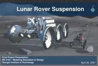
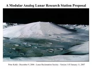
( *** for private circulation only). LUNAR ROVER Concept proposal meeting. Dr. Ashish Dutta Indian Institute of Technology Kanpur Kanpur, INDIA. Chandrayan 1 : mapping the moon Chandrayan 2: landing a mobile robot for experiments on moon.

E N D
( *** for private circulation only) LUNAR ROVER Concept proposal meeting Dr. Ashish Dutta Indian Institute of Technology Kanpur Kanpur, INDIA
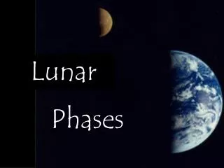
Chandrayan 1: mapping the moonChandrayan 2: landing a mobile robot for experiments on moon
1. Introduction: Chandrayan 2 PSLV-Lander-Rover ROVER LANDER
Many Challenges • Lunar gravity • Cosmic radiation • Extreme temperature -180 to 220 C • Difficult terrain : dust, craters, rocks • Time lag in control 2 secs • Flying dust, clouds cameras • Communication with earth
1. Rover structure Structural design (frame) Materials for construction Wheels & Legs? How many wheels? Electronics enclosure and insulation Vibration suppression Position of arm, cameras
2. Drive system Motors (DC brush less ) Sensors (position, acceleration?) Leg/wheel mechanism Steering motor system: located at wheel base Tyres : rubber , Ti wire based
3. Control System Motor controllers – PID ? Processor requirements I/O considerations Memory Considerations Power requirements. Central controller.
4. Sensor System for Navigation Vision based navigation Path planning Obstacle detection (laser, ultrasonic ) Self localization based on Lander coordinates
5. Communication System • Antenna Design • Transceiver 6. Thermal System • Passive thermal system. • Active thermal System. 7. Power system • Solar batteries. • Recharging and monitoring. • Power regulation. • Batteries: Nickel-Cd, Silver-Zn ?
8. Lander interface • Mechanical interface (to hold rover in position) • Electrical interface. 9. Arm Manipulator • DOF (5 DOF ?) • Requirements (Cleaning solar panels, digging, etc.) • Structure
10. Rover Operations • Start up procedures • Motor and arm initialization procedures • Rover deployments • Robot arm cleaning • Sample collecting + testing 11. Failure diagnostics and recovery • Possible modes of failure • Recovery • Back up
Main focus based on our strengths in IITK • Robot design and vision based control • Vision based control of rover • Coordinated wheel control with slip • Vision based navigation • Thermal management using – heat pipes
IITK WORK SCHEDULE • Design of rover with robot arm and its fabrication. • Multi wheel coordination control with active slip compensation • Visual map generation of lunar surface and navigation. • Visual control of arm and rover. • Development of test set up at IITK. • Development of a virtual reality simulation of rover and lunar terrain. • Experimental evaluation of developed rover
Future directions • Possible route for developing indigenous strength in this area. • Design of advanced future rovers. - Legged vehicles. - Hybrid : leg and wheels based rovers.
Strengths of IIT Kanpur • Vision based navigation and robot control. • Hardware development. • Large number of systems developed : both wheeled and legged. • Computational aspects of robotics. • Sensor development and integration.
Functional specifications from VSSC • MOBILE ROBOT STRUCTURE: ACCEPTABILITY / TESTING a. kinematic alternatives simulation b. minimum clearance test bed with obstacles c. wheel assembly unit: * traction, control, payload wheel assembly test bed * steering accuracy test under load d. control system response measurement e. power budget subunits / total power testing f. solar panels: deployment+cleaning e. payload / stability ramped terrain 2. VISION-BASED NAVIGATION: a. design validation simulation b. path planning testing ground truth comparison c. terrestrial testing trajectory measurement test bed d. accuracy / reliability repeated path point testing e. contingency / recovery
Further testing at VSSC • Level 2 : integrated functional testing / terrestrial robustness • Level 3 : thermal testing / radiation test • Level 4 : fully space qualified system