Download
1 / 20
410 likes | 1.22k Views
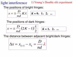
Interference of Light Waves. Conditions for interference Young’s double slit experiment Intensity distribution of the interference pattern Phasor representation Reflection and change of phase Interference in thin films. Conditions for Interference.

E N D
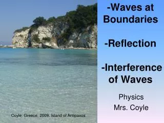
Interference of Light Waves • Conditions for interference • Young’s double slit experiment • Intensity distribution of the interference pattern • Phasor representation • Reflection and change of phase • Interference in thin films
Conditions for Interference • If two waves have a definite phase relationship then they are coherent. • Otherwise, they are incoherent (ex: two light bulbs). • For Interference: • The sources must be coherent. • The sources should be monochromatic.
Constructive interference Destructive interference
Intensity Distribution of the Interference Pattern • Interference depends on the relative phase of the two waves. • It also depends on the path difference between them. • The resultant intensity at a point is proportional to the square of the resultant electric field at that point. not
An interference pattern is formed on a screen by shining a planar wave on a double- slit arrangement (left). If we cover one slit with a glass plate (right), the phases of the two emerging waves will be different because the wavelength is shorter in glass than in air. If the phase difference is 180°, how is the interference pattern, shown left, altered? 1. The pattern vanishes. 2. The bright spots lie closer together. 3. The bright spots are farther apart. 4. There are no changes. 5. Bright and dark spots are interchanged.
Phasors for Several Waves • Represent waves by phasors, remembering to maintain proper phase relationships between them. • The resultant phasor, ER, is the vector sum of the individual phasors. The phase angle, a, is the phase angle between ER and the first phasor.
Change of Phase in Reflection The positions of the fringes are reversed compared to Young’s experiment An EM wave undergoes a phase change of 180° upon reflection from a medium that has a higher index of refraction than the one in which it is traveling.
Interference in Thin Films • A wave traveling from a medium of index of refraction of n1 towards a medium with index of refraction of n2 undergoes a 180° phase change upon reflection if n2 > n1 and no phase change if n2 < n1. • The wavelength of light ln in a medium with index of refraction n is given by, ln = l / n. For constructive interference m = 0,1,2,… For destructive interference m = 0,1,2,…
Two identical slides in air are illuminated with monochromatic light. The slides are exactly parallel, and the top slide is moving slowly upward. What do you see in top view? 1. all black 2. all bright 3. fringes moving apart 4. sequentially all black, then all bright 5. none of the above
Newton’s Rings For destructive interference For constructive interference
Non-reflective Coatings Since both paths have the same phase change at the interfaces, take only the path differences into account. For destructive interference t Example: l = 550 nm, no reflection
Monochromatic light shines on a pair of identical glass microscope slides that form a very narrow wedge. The top surface of the upper slide and the bottom surface of the lower slide have special coatings on them so that they reflect no light. The inner two surfaces (A and B) have nonzero reflectivities. A top view of the slides looks like 1. I. 2. II.
Interference in a Wedge Shaped Film Destructive interference at the tip because of 180° phase change for the front surface and no phase change for the back surface. For destructive interference For constructive interference