Download
1 / 1
10 likes | 121 Views
1. 10. A. 11. A. 2. 3. 4. 5. 6. 7. 8. 9. Fig. 1b) Section A-A. Fig. 1a) Heating Stage Installed Inside ESEM. 1 – Stainless Steel Heat Shield2 – Stainless Steel Cover3 – Alumina Crucible4 – Heater5 – Upper Zircar Block

E N D
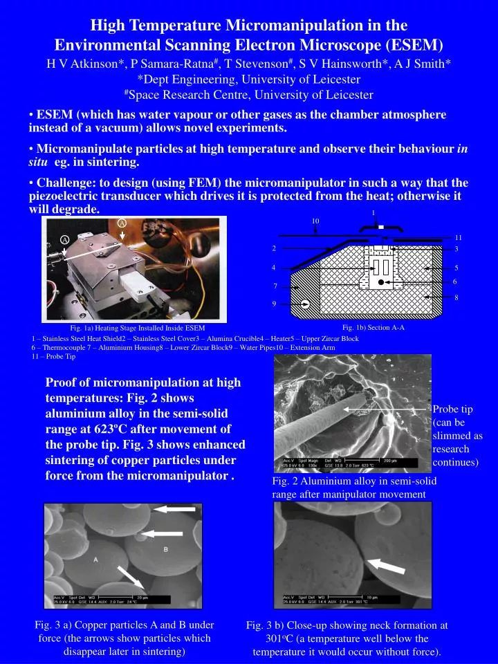
1 10 A 11 A 2 3 4 5 6 7 8 9 Fig. 1b) Section A-A Fig. 1a) Heating Stage Installed Inside ESEM 1 – Stainless Steel Heat Shield2 – Stainless Steel Cover3 – Alumina Crucible4 – Heater5 – Upper Zircar Block 6 – Thermocouple 7 – Aluminium Housing8 – Lower Zircar Block9 – Water Pipes10 – Extension Arm 11 – Probe Tip High Temperature Micromanipulation in the Environmental Scanning Electron Microscope (ESEM) H V Atkinson*, P Samara-Ratna#, T Stevenson#, S V Hainsworth*, A J Smith* *Dept Engineering, University of Leicester #Space Research Centre, University of Leicester • ESEM (which has water vapour or other gases as the chamber atmosphere instead of a vacuum) allows novel experiments. • Micromanipulate particles at high temperature and observe their behaviour in situ eg. in sintering. • Challenge: to design (using FEM) the micromanipulator in such a way that the piezoelectric transducer which drives it is protected from the heat; otherwise it will degrade. Proof of micromanipulation at high temperatures: Fig. 2 shows aluminium alloy in the semi-solid range at 623ºC after movement of the probe tip. Fig. 3 shows enhanced sintering of copper particles under force from the micromanipulator . Probe tip (can be slimmed as research continues) Fig. 2 Aluminium alloy in semi-solid range after manipulator movement Fig. 3 a) Copper particles A and B under force (the arrows show particles which disappear later in sintering) Fig. 3 b) Close-up showing neck formation at 301oC (a temperature well below the temperature it would occur without force).