Download
1 / 59
590 likes | 719 Views
CBSE – Lecture 3. Components and concepts Main text: Ian Sommerville, Software Engineering , 8 th edition, chapter 19.1 ( Components and component models ) Additional reading:

E N D
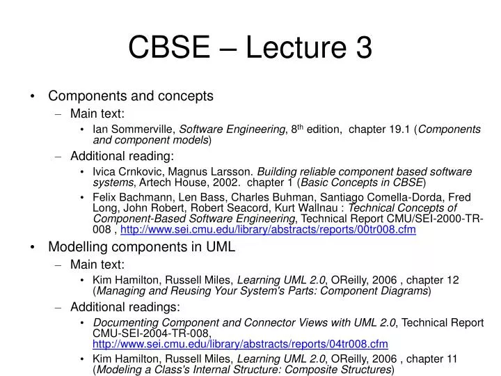
CBSE – Lecture 3 • Components and concepts • Main text: • Ian Sommerville, Software Engineering, 8th edition, chapter 19.1 (Components and component models) • Additional reading: • Ivica Crnkovic, Magnus Larsson. Building reliable component based software systems, Artech House, 2002. chapter 1 (Basic Concepts in CBSE) • Felix Bachmann, Len Bass, Charles Buhman, Santiago Comella-Dorda, Fred Long, John Robert, Robert Seacord, Kurt Wallnau : Technical Concepts of Component-Based Software Engineering, Technical Report CMU/SEI-2000-TR-008 , http://www.sei.cmu.edu/library/abstracts/reports/00tr008.cfm • Modelling components in UML • Main text: • Kim Hamilton, Russell Miles, Learning UML 2.0, OReilly, 2006 , chapter 12 (Managing and Reusing Your System's Parts: Component Diagrams) • Additional readings: • Documenting Component and Connector Views with UML 2.0, Technical Report CMU-SEI-2004-TR-008, http://www.sei.cmu.edu/library/abstracts/reports/04tr008.cfm • Kim Hamilton, Russell Miles, Learning UML 2.0, OReilly, 2006 , chapter 11 (Modeling a Class's Internal Structure: Composite Structures)
Component based development • “Systems should be assembled from existing components” • Idea dates since 1968: Douglas McIllroy: “Mass produced software components” • Component-based software engineering (CBSE) is an approach to software development that relies on software reuse. • Component Based Software Engineering (CBSE) = reuse of: • Subsystems • Infrastructure • Goals of CBSE: • Development of system = assembly of component • Maintenance,upgrading=customization, replacement of components • More then reuse: support for flexibility • Substitutability: replacing a component (a part of an implementation) with another. • Issue: how do we know that the new component fits in place of the old one ? (problem of specification) • Extensibility: adding/removing components • Issue: extensible architectures; dynamic architectures • Happening at Run-time ! • Issue: infrastructure needed to enable run-time composition
Component based software construction – the ideal case Application Software construction vs. creation: application is developed as an assembly of “integrated circuits”
Component interactions Components must obey to common conventions or standards ! Only in this way they will be able to recognise each others interfaces and connect and communicate to each other
CBSE essentials • Independent components specified by their interfaces. • Separation between interface and implementation • Implementation of a component can be changed without changing the system • Component standards to facilitate component integration. • Component models embody these standards • Minimum standard operations: how are interfaces specified, how communicate components • If components comply to standards, then their operation may be independent of their programming language • Middleware that provides support for component inter-operability. • Provides support for component integration • Handles component communication, may provide support for resource allocation, transaction management, security, concurrency • A development process that is geared to reuse.
CBSE and design principles • Apart from the benefits of reuse, CBSE is based on sound software engineering design principles that support the construction of understandable and maintainable software: • Components are independent so they do not interfere with each other; • Component implementations are hidden so they can be changed without affecting others; • Communication is through well-defined interfaces so if these are maintained one component can be replaced by another that provides enhanced functionality; • Component platforms (infrastructures) are shared and reduce development costs.
CBSE problems • Component trustworthiness - how can a component with no available source code be trusted? • Component certification - who will certify the quality of components? • Emergent property prediction - how can the emergent properties of component compositions be predicted? • Requirements trade-offs - how do we do trade-off analysis between ideal requirements and available components ?
Component definitions - Szyperski • Szyperski: • “A software component is a unit of composition with contractually specified interfaces and explicit context dependencies only. A software component can be deployed independently and is subject to composition by third-parties.”
Component definitions – Councill and Heinemann • Councill and Heinmann: • “A software component is a software element that conforms to a component model and can be independently deployed and composed without modification according to a composition standard.”
Component characteristics 1 Fig. 19.1 from [Sommerville]
Component characteristics (cont) Fig. 19.1 from [Sommerville]
Component interfaces • An interface of a component can be defined as a specification of its access point, offering no implementation for any of its operations. • This seperation makes it possible to: • Replace the implementation part without changing the interface; • Add new interfaces (and implementations) without changing the existing implementation • A component has 2 kinds of interfaces: • Provides interface • Defines the services that are provided by the component to the environment / to other components. • Essentially it is the component API • Mostly methods that can be called by a client of the component • Requires interface • Defines the services that specifies what services must be made available by the environment for the component to execute as specified. • If these are not available the component will not work. This does not compromise the independence or deployability of the component because it is not required that a specific component should be used to provide these services
Component interfaces Fig. 19.2 from [Sommerville]
Example: A data collector component Fig. 19.3 from [Sommerville]
Describing interfaces • Interfaces defined in standard component technologies using techniques such as Interface Definition Language (IDL) are: • Sufficient in describing functional properties. • Insuffiecient in describing extra-functional properties such as quality attributes like accuracy, availability, latency, security, etc.
Contracts • A more accurate specification of a component's behavior can be achieved through contracts. • A contract is comprised of: • The Invariant, the global constraints which the component will maintain; • The Pre-condition, the constraints which need to be met by the client; • The Post-condition, the constraints which the component promises to establish in return. • A contract specifies the interactions among components, in terms of: • The set of participating components; • The role of each component through its contractual obligations, such as type and casual obligations; • The invariant to be maintained by the components; • The specification of the methods which instantiate the contract.
Components and object classes • Components are deployable entities • They are not compiled into an application program but are installed directly on an execution platform • Components do not define types. • A class definition defines an abstract data type and objects are instances of that type. A component is an instance, not a template • Components don’t have state • This is accordingly to Szyperski's definition of a component. However, there are component models that allow stateful components ! • Component implementations are opaque. • Components are completely defined by their interfaces • They are often delivered as binary units • Components are language-independent. • Object classes are written in one particular OO programming language and can only interoperate with classes written in the same language • Components may be implemented in an OO way or NOT ! • Components are standardised. • Unlike classes that you can implement in any way components must conform to some component model that constrains their implementation
Component models • A component model is a definition of standards for component implementation, documentation and deployment. • These standards are for: • component developers to ensure that components can interoperate • Providers of component executioninfrastructures who provide middleware to support component operation • Examples of component models • EJB model (Enterprise Java Beans) • COM+ model (.NET model) • Corba Component Model • The component model specifies how interfaces should be defined and the elements that should be included in an interface definition.
Elements of a component model Fig. 19.4 from [Sommerville]
Middleware support • Component models are the basis for middleware that provides support for executing components. • Component model implementations provide shared services for components: • Platform services that allow components written according to the model to communicate; • Horizontal services that are application-independent services used by different components. • To use services provided by a componrnt model infrastructure, components are deployed in a container. This is a set of interfaces used to access the service implementations.
Component model services Fig. 19.5 from [Sommerville]
Architecture of Component Models Platform Services: allow components written according to the model to communicate; locating, linking, replacing components Component Component Component Component platform (component framework) Operating System Middleware Horizontal Services: application-independent services used by different components. Concurrency, security, transaction management, Resource management Hardware
Software Frameworks • CBSE: building software = "putting pieces together" • Frameworks: provide the context in which the pieces can be used • A framework may be seen as: • A reusable design of a system • A skeleton of an application which can be customized by an application developer • A microarchitecture which provides an incomplete template for systems within a speciffic domain
The component framework forces components to perform their tasks via mechanisms controlled by the framework
Standards: component types, interfaces, allowable patterns of interaction
Frameworks vs. Contracts • Both describe how groups of participating components interact with each other • Frameworks focus on the overall properties of component compositions. • Contracts give specifications for relationships between concrete components.
Component development for reuse • Components developed for a specific application usually have to be generalised to make them reusable. • A component is most likely to be reusable if it associated with a stable domain abstraction (business object). • For example, in a hospital stable domain abstractions are associated with the fundamental purpose - nurses, patients, treatments, etc.
Component development for reuse • Components for reuse may be specially constructed by generalising existing components. • Component reusability • Should reflect stable domain abstractions; • Should hide state representation; • Should be as independent as possible; • Should publish exceptions through the component interface. • There is a trade-off between reusability and usability • The more general the interface, the greater the reusability but it is then more complex and hence less usable.
Changes for reusability • Remove application-specific methods. • Change names to make them general. • Add methods to broaden coverage. • Make exception handling consistent. • Add a configuration interface for component adaptation. • Integrate required components to reduce dependencies.
Legacy system components • Existing legacy systems that fulfil a useful business function can be re-packaged as components for reuse. • This involves writing a wrapper component that implements provides and requires interfaces then accesses the legacy system. • Although costly, this can be much less expensive than rewriting the legacy system.
Reusable components • The development cost of reusable components may be higher than the cost of specific equivalents. This extra reusability enhancement cost should be an organization rather than a project cost. • Generic components may be less space-efficient and may have longer execution times than their specific equivalents.
The component: Architectural point of view • “The software architecture of a program is the structure or structures of the system, which comprise software components and connectors, the externally visible properties of these components and the relationships among them” • Bass, Clements, Kazman, Software Architecture in Practice.
Example: Component-Connector architectural structure • Components: represent the principal computational elements and data stores of a system. A component has ports, which define the points of interaction between that component and its environment. • Connectors: identify the pathways of interaction between components. Connectors may represent simple interactions or even complex protocols A connector defines a set of roles that identify the participants in the interaction. • An architectural configuration is a graph that defines how a set of components are connected to each other via connectors. The graph is defined by associating component ports with the connector roles in which they participate
Component model and architecture Component Model: Types (shapes) of building blocks System: Architecture: specific functional blocks and their assembly
Generic Comp Every component fits at every place Design of components is independent Architectural vs Generic Components • Architectural Comp • There is exactly one component that fits each place in the system • Design of components is coordinated Framework Comp Several components fit at a particular place in the system Design of components is scoped
UML Components • Based on: Kim Hamilton, Russell Miles, Learning UML 2.0, OReilly, 2006 , chapter 12 • Components are used in UML to organize a system into manageable, reusable, and swappable pieces of software. • UML component diagrams model the components in your system and as such form part of the development view • The development view describes how your system's parts are organized into modules and components and is great at helping you manage layers within your system's architecture.
UML Components • In UML, a component can do: • the same things a class can do: generalize and associate with other classes and components, implement interfaces, have operations, and so on. • Furthermore, as with composite structures, components can have ports and show internal structure. It's common for a component to contain and use other classes or components to do its job. • To promote loose coupling and encapsulation, components are accessed through interfaces.
A basic component in UML • A component is drawn as a rectangle with the <<component>> stereotype and an optional tabbed rectangle icon in the upper righthand corner. • Figure 12-2 shows a ConversionManagement component used in the CMS that converts blogs to different formats and provides feeds such as RSS feeds. • In earlier versions of UML, the component symbol was a larger version of the tabbed rectangle icon • You can show that a component is actually a subsystem of a very large system by replacing <<component>> with <<subsystem>>, as shown in Figure 12-3. • UML considers a subsystem a special kind of component and is flexible about how you use this stereotype, but it's best to reserve it for the largest pieces in your overall system, such as a legacy system that provides data or a workflow engine in the CMS. Fig. 12.2 and 12.3 from [UML2]
Provided and required interfaces • Components need to be loosely coupled so that they can be changed without forcing changes on other parts of the system - this is where interfaces come in. Components interact with each other through provided and required interfaces to control dependencies between components and to make components swappable. • A provided interface of a component is an interface that the component realizes. Other components and classes interact with a component through its provided interfaces . A component's provided interface describes the services provided by the component. • A required interface of a component is an interface that the component needs to function. More precisely, the component needs another class or component that realizes that interface to function. But to stick with the goal of loose coupling, it accesses the class or component through the required interface. A required interface declares the services a component will need. • There are three standard ways to show provided and required interfaces in UML: • ball and socket symbols • stereotype notation • text listings.
Ball and socket notation for interfaces Fig. 12.4 from [UML2]
Stereotype notation for interfaces Fig. 12.5 from [UML2]
Listing component interfaces This notation additionaly has an <<artifacts>> section listing the artifacts or physical files manifesting this component Fig. 12.6 from [UML2]
Showing components working together If a component has a required interface, then it needs another class or component in the system that provides it. At a higher level view, this is a dependency relation between the components Fig. 12.7, 12.8 and 12.9 from [UML2]
Example- component diagram presents system architecture Fig. 12.10 from [UML2]
Classes that realize a component A component often contains and uses other classes to implement its functionality. Such classes are said to realize a component. There are 3 ways to depict this: Fig. 12.12 , 12.13, 12.14 from [UML2]
Ports and internal structure • There is heavy overlap between certain topics in component diagrams and composite structures. The ability to have ports and internal structure is defined for classes in composite structures. Components inherit this capability and introduce some of their own features, such as delegation and assembly connectors. • The topics of a class's internal structure and ports in the context of composite structures are presented here first (based on Chapter 11 from [UML2] .
Composite structures • Composite structures show: • Internal structures • Show the parts contained by a class and the relationships between the parts; this allows you to show context-sensitive relationships, or relationships that hold in the context of a containing class • Ports • Show how a class is used on your system with ports • Collaborations • Show design patterns in your software and, more generally, objects cooperating to achieve a goal • Composite structures provide a view of your system's parts and form part of the logical view of your system's model