Download
1 / 94
1.62k likes | 2.68k Views
MATERIALS SCIENCE & ENGINEERING. Part of. A Learner’s Guide. AN INTRODUCTORY E-BOOK. Anandh Subramaniam & Kantesh Balani Materials Science and Engineering (MSE) Indian Institute of Technology, Kanpur- 208016 Email: anandh@iitk.ac.in, URL: home.iitk.ac.in/~anandh.

E N D
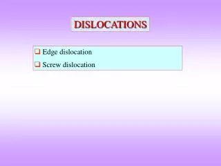
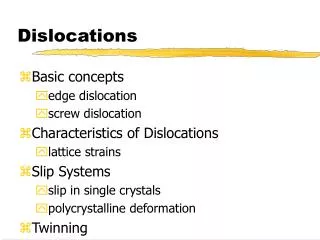
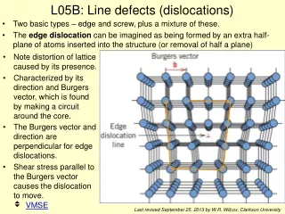
MATERIALS SCIENCE & ENGINEERING Part of A Learner’s Guide AN INTRODUCTORY E-BOOK Anandh Subramaniam & Kantesh Balani Materials Science and Engineering (MSE) Indian Institute of Technology, Kanpur- 208016 Email:anandh@iitk.ac.in, URL:home.iitk.ac.in/~anandh http://home.iitk.ac.in/~anandh/E-book.htm DISLOCATIONS • Edge dislocation • Screw dislocation • Dislocations in crystals Further reading Introduction to Dislocations D. Hull and D.J. Bacon Pergamon Press, Oxford (1984) Advanced reading (comprehensive) Theory of DislocationsJ. P. Hirth and J. Lothe McGraw-Hill, New York (1968) Recommended website http://www.tf.uni-kiel.de/matwis/amat/def_en/
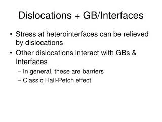
As seen before dislocations are 1D (line) defects • The role of dislocations goes far beyond just ‘plasticity by slip’ • They play an important role in a variety of deformation processes like creep, fatigue and fracture • They can play a ‘constructive role’ in crystal growth • They can provide short circuit paths for diffusion (pipe diffusion) • Understanding the importance of dislocations in material behaviour cannot be overstated → hence it is very important to thoroughly understand the structure and behaviour of dislocations
Dislocations • The importance of understanding dislocations and their effect on material behaviour cannot be overstated. • Though often the importance of dislocations in the context of plastic deformation* by slip** is highlighted; its role in materials science is far greater. (The next slide shows some of these roles). • In this context it is important to note that even in crystalline materials there are alternate mechanisms of plastic deformation (as shown in an upcoming slide)→ Twinning*** also being an important one. • The important thing to be kept in mind is the role of dislocations in weakening crystals (taken up after the above mentioned slides). * Plastic deformation → permanent deformation that remains when all external loading/constraints are removed ** Slip→ is a technical term referring to plastic deformation caused by dislocations ◘ the ‘first step’ of the process is the small surface step which is created when a dislocation leaves a crystal *** Twinning → process by which one part of the crystal gets related to another part, by a symmetry operator (usually a mirror); which is not a symmetry operator of the crystal.
Path to understanding the role of Dislocations in material behaviour Consider a dislocation in in an infinite crystal Stress fields, strain fields, energy etc. Take into account finite crystal effects Though these points are written as a sequence many of these have to be considered in parallel Free surfaces, grain boundaries etc. Consider interaction of dislocations with other defects Interactions with other dislocations, interstitials, precipitates etc. Collective behaviour and effects of external constrains Long range interactions & collective behaviour & external constraints** • Static and dynamic effects and interactions should be included* * Dynamic effects include: (Altered) Stress field of a moving dislocation Interactions evolving in time Note: the above step by step method may often not be the most practical one and there are techniques which take up collective behaviour directly
Cross - slip Creep Dislocation climb mechanisms in crystalline Vacancy diffusion materials Grain boundary sliding Role of Dislocations Kinetics Deformation Processes Diffusion(Pipe) Creep Crystal Growth(Screw dislocation) Fatigue Fracture Slip Structural Incoherent Twin Grain boundary(low angle) Semicoherent Interfaces Disc of vacancies ~ edge dislocation and more…!! Note: Structural dislocations can also play a role in deformation and kinetic processes
Though plasticity by slip is the most important mechanism of plastic deformation, there are other mechanisms as well (plastic deformation here means permanent deformation in the absence of external constraints): Plastic Deformation in Crystalline Materials Creep Mechanisms Slip(Dislocation motion) Twinning Phase Transformation Grain boundary sliding + Other Mechanisms Vacancy diffusion Grain rotation Dislocation climb Note: Plastic deformation in amorphous materials occur by other mechanisms including flow (~viscous fluid) and shear banding
Weakening of a crystal by the presence of dislocations • To cause plastic deformation by shear (all of plastic deformation by slip require shear stresses at the microscopic scale*) one can visualize a plane of atoms sliding past another (fig below**) • This requires stresses of the order of GPa (calculation in the next slide) • But typically crystals yield at stresses ~MPa • This implies that ‘something’ must be weakening them drastically • It was postulated in 1930s# and confirmed by TEM observations in 1950s, that the agent responsible for this weakening are dislocations * Even if one does a pure uniaxial tension test with the tension axis along the z- axis, except for the horizontal and the vertical planes all other planes ‘feel’ shear stresses on them ** As to how this atomic slip is connected to macroscopic permanent shape changes will be considered later # By Taylor, Orowan and Polyani
Plastic deformation of a crystal by shear Let us consider the shearing of an entire plane of atoms over one another → causing plastic deformation by shear Entire row of atoms sliding past another Final configuration Starting configuration m Sinusoidal relationship The shear stress displacement curve looks as shown in the diagram on the right Realistic curve
As a first approximation the stress-displacement curve can be written as At small values of displacementHooke’s law should apply For small values of x/b Hence the maximum shearstress at which slip should occur If b ~ a • The theoretical shear stress will be in the range 3 – 30 GPa ~
The shear modulus of metals is in the range 20 – 150 GPa • The theoretical shear stress will be in the range 3 – 30 GPa ~ • Actual shear stress is 0.5 – 10 MPa (experimentally determined) • I.e. (Shear stress)theoretical > 100 (Shear stress)experimental!!!! DISLOCATIONS Dislocations severely weaken the crystal Whiskers of metals (single crystal free of dislocations, Radius ~ 106m) can approach theoretical shear strengths Whiskers of Sn can have a yield strength in shear ~102 G (103 times bulk Sn)
As we have seen before dislocations can play diverse kinds of role in materials structure and its behaviour • Perhaps the most important of these is the weakening of the crystal in the presence of dislocations • From a slide before we know the path to understanding the role of dislocations in materials involves their interactions with other dislocations and defects present in the material (and the evolution of the system with time/deformation)→ This path will include the ‘hardening’ of the crystal, i.e strengthening of the weakened crystal→ In this context it will be noted that many dislocations will interact with each other and there will be a strengthening effect Dislocations: path breaking ideas • As late as 1930 the reason behind this weakening of the crystal was not clear (to imagine that this was the post Relativity, post Quantum Mechanics era, wherein deep questions regarding the larger scale of the universe and the sub-atomic realms were being conquered → but why a rod of copper can be bent easily was not known!) • Taylor, Orowan and Polanyi (independently) postulated the presence of dislocations as a mechanism leading to the weakening of the crystal • The continuum construction of a dislocation (and other defects) was proposed by Volterra in 1905. • The presence of dislocations was Electron microscopically confirmed in the 1950s • ◘ G.I. Taylor, Proceedings of the Royal Society A, 145 (1934) 362. ◘ E. Orowan, Zeit. Physics, 89 (1934) 605. ◘ N. Polanyi, Zeit. Phys. 89 (1934) 660. • Vito Volterra, 1905.
The analogy usually given to understand the role of dislocations in weakening a crystal is the one of ‘pulling a carpet’. • If one tries to pull an entire carpet (a long and wide one), by sliding it against the floor, the effort required is large. • However, if a ‘bump’ is made in the carpet (as in the figure in the following slide) and this bump is moved across the length of the carpet, then the carpet moves forward by a small distance (as provided by the bump). • The force required to move the bump will be considerably small as compared to the force required to pull the entire carpet. • By creating and moving a series of bumps successively the carpet can be moved forward ‘bit by bit’. (Graphic on next slide).
The Volterra Dislocation Continuum description of a dislocation • The continuum* concept of a dislocation (and other defects) was proposed by Vito Volterra in 1905. • His ideas and calculations based on his ideas predate their application to crystals. However, continuum calculations based on Volterra’s idea are used even today to understand the behaviour of dislocations in crystals. • Continuum calculations of stress fields, displacement fields etc. related to dislocations are found to be valid to within a few atomic spacing (i.e. the continuum description fails only within about 5 atomic diameters/Burgers vector). • In this chapter the stress fields of dislocations shown are based on elastic continuum theories.** * Continuum implies that we are not ‘worried’ about atoms! (Antonym Discretum). ** This is a ‘strange’ aspect: we have used elasticity theory to calculate the stress fields of the very (most important) agent responsible for plastic deformation
Deformations of a hollow cylinder showing the formation of various defects (Volterra constructions) Edge dislocations Dislocations Disclinations Perfect cylinder Screw dislocation Disclinations
DISLOCATIONS EDGE SCREW MIXED • If one looks at a sample of Aluminum under a TEM, one usually finds curved dislocation lines Usually dislocations have a mixed character and Edge andScrewdislocations are the ideal extremes. • Not only this, the character of the dislocation (i.e the percentage of screw and percentage of edge character) will change from position to position along the dislocation line. • However, under special circumstances Pure Edge, Pure Screwora Mixed Dislocation with a fixed percentage of edge character can form.(e.g. in GeSi epitaxial films on Si substrate 60 misfit dislocations form- i.e. the dislocation lines are straight with the angle between b and t being 60)→ more about these aspects will be considered later • The edge dislocation is easier to visualize and hence many of the concepts regarding dislocations will be illustrated using the example of the pure edge dislocation. TEM micrograph showing dislocation lines Dislocation lines
Dislocation can be considered as a boundary between the slipped and the unslipped parts of the crystal lying over a slip plane* Slippedpartof thecrystal Unslippedpartof thecrystal * this is just a way of visualization and often the slipped and unslipped regions may not be distinguished
A dislocation has associated with it two vectors: • The Burgers vector is like the ‘SOUL of a dislocation’. It ‘can be defined’ even if there is no dislocation in the crystal (it is the shortest lattice translation vector for a full/perfect dislocation), it defines every aspect of the dislocation (its stress fields, energy, etc.) and expresses itself even in the ‘death’ of the dislocation (i.e. when the dislocation leaves the crystal and creates a step of height ‘b’). • Burgers vector is the shortest translation vector (for a full/perfect dislocation) and can be determined by the Burgers circuit (coming up). • Hence, Burgers vector is an invariant for a crystal, while the line vector is not. If one looks at a transmission electron micrograph showing a dislocation line in Aluminium, it will not be straight i.e. the line vector is not fixed (usually). TEM micrograph showing dislocation lines Dislocation lines
Burgers Vector Edge dislocation Determination of Burgers vector in a dislocated crystal using Right Hand Finish to Start Rule (RHFS) • In a perfect crystal make a circuit (e.g. as in the figure shown: 8 atomic steps to right, 7 down, 8 left & 7 up). The circuit is Right Handed. • Do the same in the same in the dislocated crystal. The ‘missing link’ (using some convention like RHFS) is the Burgers vector. RHFS: Right Hand Finish to Start convention Note: the circuit is drawn away from the dislocation line
Some models of Edge Dislocation Video: Edge Dislocation Model using magnetic balls(not that accurate!)
Understanding the Edge dislocation • The edge dislocation is NOT the ‘extra half-plane’, it is neither the ‘missing half-plane’→ it is the line between the ‘extra’ and the ‘missing’ half-planes. • The regions far away from the dislocation line are perfect → all the ‘deformation’ is concentrated around the dislocation line. • However, the stress field of the dislocation is a ‘long range’ field. Note: • The Burgers vector has been drawn away form the dislocation line (sometimes it may be drawn close to dislocation line for convenience). • The dislocation line is between the ‘missing’ and ‘extra’ half-plane.
Edge dislocation • Often to visualize the edge dislocation, only the extra ‘half’-plane and slip plane are shown. The remaining crystal is hidden away. • The intersection of the extra half-plane and slip plane can be visualized as the dislocation line (one of the two possible directions is represents the line vector- shown in blue colour). Dislocation line
Dislocation can be considered as the boundary between the slipped and the unslipped parts of the crystal lying over a slip plane. • The intersection of the extra half-plane of atoms with the slip planedefines the dislocation line (for an edge dislocation). • Direction and magnitude of slip is characterized by the Burgers vectorof the dislocation (A dislocation is born with a Burgers vector and expresses it even in its death!). • The Burgers vector can be determined by the Burgers Circuit. • Right hand screw (finish to start) convention is usually used for determining the direction of the Burgers vector. • As the periodic force field of a crystal requires that atoms must move from one equilibrium position to another b must connect one lattice position to another (for a full dislocation). • Dislocations tend to have as small a Burgers vector as possible. • Dislocations are non-equilibrium defects and would leave the crystal if given an opportunity.
Screw dislocation Slip Plane Note: The figure shows a Right Handed Screw (RHS) dislocation
Geometric properties of dislocations • In a edge dislocation : b is perpendicular to t • In a screw dislocation : b is parallel to t • Other properties are as in the table below
Model of Screw Dislocation Though it is difficult to understand anything from the photo of the model!
Mixed dislocations Dislocations with mixed edge and screw character • As we had noted, except in special circumstances, dislocations have mixed edge and screw character. • In a curved dislocation the edge and screw character change from point to point. • Typically in a dislocation loop only ‘points’ have pure edge or pure screw characterEdge: b tScrew: b || t. Vectors defining a dislocation RHS b Red line is the loop +ve Edge ve Edge Slip Plane LHS
Let us consider a ‘quarter’ of a loop E S Pure Edge Pure screw Except for points S and E the remaining portion of the dislocation line has a mixed character
Edge and Screw components: the ‘usual’ way to get the effective Burgers vector The b vector is resolved into components: ‘parallel to t’ → screw component and ‘perpendicular to t’ → edge component Screw component Edge component Edge component Components of the mixed dislocation at P Screw Component
Edge and Screw components: different way to visualize the orientation of the effective half-plane Instead of resolving the b vector if the t vector is resolved to find the edge and screw components For an edge dislocation the extra half-plane contains the t vector → by resolving the t vector the edge component of the t vector t.cos lies in the “effective” half-plane* (Figure below) *Note: For a mixed dislocation there is no distinct ‘half-plane’
Edge and Screw components- the effective half-plane: a ‘crude’ anology to understand the orientation of the extra half plane Assume water is flowing from left to right onto a rigid curved wall (in red colour below). The green portion of the wall ‘feels’ only shear stresses, while the maroon portion feels only normal stresses (of magnitude b). A point M (in the curved segment) feels both normal and shear stresses. The effective part which feels normal stresses is oriented vertically with magnitude bCos. M
Motion of Dislocations • Two kinds of motion of a dislocation are possible: Glide and Climb. • First we consider glide motion. • Dislocations may move under an externally applied force (resulting in stress inside the material- often casually referred to ‘applied stress’). • At the local level shear stresses on the slip plane can only drive dislocations. • The minimum stress required to move a dislocation is called the Peierls-Nabarro (PN) stress or the Peierls stress or the Lattice Friction stress (i.e the externally ‘applied stress’ may even be purely tensile but on the slip plane shear stresses must act in order to move the dislocation). • Dislocations may also move under the influence of other internal stress fields (e.g. those from other dislocations, precipitates, those generated by phase transformations etc.). • Dislocations are attracted to free-surfaces (and interfaces with softer materials) and may move because of this attraction → this force is called the Image Force. • In any case the Peierls stress must be exceeded for the dislocation to move. • The value of the Peierls stress is different for the edge and the screw dislocations. • The first step of plastic deformation can be considered as the step created when the dislocation moves and leaves the crystal.→ “One small step for the dislocation, but a giant leap for plasticity”. • When the dislocation leaves the crystal a step of height ‘b’ is created → with it all the stress and energy stored in the crystal due to the dislocation is relieved. Click here to know more about Peierls Stress More about the motion of dislocations in the chapter on plasticity
Conservative (Glide) Motion of dislocations On the slip plane Motion of Edge dislocation Non-conservative(Climb) Motion of dislocation to the slip plane • For edge dislocation: as b t→ they define a plane → the slip plane • Climb involves addition or subtraction of a row of atoms below the half plane ► +ve climb = climb up → removal of a plane of atoms ► ve climb = climb down → addition of a plane of atoms
Edge Dislocation Glide Motion of an edge dislocation leading to the formation of a step (of ‘b’) Shear stress Surface step(atomic dimensions) Graphics Motion of Edge Dislocation
Motion of a screw dislocation leading to a step of b Graphics Video: Motion of Screw Dislocation Note: Schematic diagrams
Surface step When the dislocation leaves the crystal the stress field associated with it is relieved. However, it costs some energy to create the extra surface corresponding to the step • Are these steps visible?These steps being of atomic dimensions are not visible in optical microscopes. However, if many dislocations operate on the same slip plane then a step of nb (n~ 100s-1000s) is created which can even be seen in an optical microscope (called the slip lines).
Dislocations leaving the slip plane • As it was observed the ‘first step’ of plastic deformation is the motion of a dislocation leaving the crystal (or to some other interface bounding the crystal) → leading to the formation of a step. • For continued plastic deformation it is necessary that dislocations continue to move and leave the crystal. Hence, any impediments to the motion of a dislocation will lead to ‘hardening’ of the crystal and would ‘stall’ plastic deformation (the pinning of a dislocation). • Once a dislocation has been pinned it can either ‘break down the barrier’ or ‘bypass’ the barrier. • Bypassing the barrier can take place by mechanisms like: Climb Cross Slip Frank-Read mechanism …. • In climb and cross slip the dislocation leaves/changes its ‘current’ slip plane and moves to another slip plane thus avoiding the barrier • However, these processes (climb and cross slip) can occur independent of the pinning of the dislocation!
Non-conservative*: involves mass transport Edge dislocation Climb Dislocation leaving/changing the slip plane Screw dislocation Cross Slip Conservative In climb an edge dislocation moves to an adjacent parallel plane, but in cross slip a screw dislocation moves to a plane inclined to the original plane. *Conservative climb is also possible!! → by motion of prismatic edge loop on the slip plane
Climb of Edge Dislocation Positive climb Removal of a row of atoms Negative climbAddition of a row of atoms Removal of a row of atoms leads to a decrease in vacancy concentration in the crystal and negative climb leads to an increase in vacancy concentration in the crystal.
Screw dislocation: Cross Slip • The figures below show the cross slip of a screw dislocation line from Slip Plane-1 (SP1) to Slip plane-2 (SP2). • This may occur if the dislocation is pinned in slip plane-1. • For such a process to occur the Resolved Shear Stress on SP1 should be greater than the Peierls stress at least (often stresses higher than the Peierls stress has to be overcome due to the presence of other stress fields). The dislocation is shown cross-slipping from the blue plane to the green plane
Funda Check How does plastic deformation by slip occur? The first step of plastic deformation by slip (at the fundamental level) is the motion of a dislocation leaving the crystal. • By externally applied force (or some other means!) stress has to be ‘generated’ within the crystal. • The slip plane should feel shear stresses. • The shear stress should exceed the ‘Critical Resolved Shear Stress (CRSS)’ or Peierls stress. • The dislocation should leave the crystal creating a surface step of height ‘b’. The process ahead of this which leads to an arbitrary shape change is complicated and we will deal with a part of it later.
Where can a dislocation line end? • Dislocation line cannot end inside the crystal (abruptly) • The dislocation line: Ends on a free surface of the crystal Ends on an internal surface or interface Closes on itself to form a loop Ends in a node • A node is the intersection point of more than two dislocations • The vectoral sum of the Burgers vectors of dislocations meeting at a node = 0 Funda Check What about the introduction of a quarter plane of atoms- doesn’t the dislocation line end inside the crystal? • As seen in the figure below there are two sections to the dislocation line ending on free surface of the crystal and hence not inside the crystal.
Positive and Negative dislocations • As we have seen when there are two are more EDGE dislocations in a slip plane one of them is assigned a +ve sign and the other one a ve sign (done arbitrarily) • In the case of screw dislocations the Right Handed Screw (RHS) Dislocation is Structurally Distinct from the Left Handed Screw (LHS) Dislocations In the case of RHS dislocation as a clockwise circuit (Burgers) is drawn then a helical path leads into the plane of the
Energy of dislocations • The presence of a dislocation distorts the bonds and costs energy to the crystal. Hence, dislocations have distortion energy associated with them • The energy is expressed as Energy per unit length of dislocation line→ Units: [J/m] • Edge → Compressive and tensile stress fields Screw → Shear stress fields • The energy of a dislocation can approximately be calculated from linear elastic theory. The distortions are very large near the dislocation line and the linear elastic description fails in this region → called the Core of the dislocation (estimates of this region range from b to 5b depending on the crystal in question). The structure and energy of the core has to be computed through other methods and the energy of the core is about 1/10 the total energy of the dislocation. • The formula given below gives reasonable approximation of the dislocation energy. Elastic Energy of dislocation Non-elastic (Core) ~E/10 E G → () shear modulus b → |b| Elastic Energy of a dislocation / unit length
As it costs energy to put a dislocation in a crystal: Dislocations tend to have as small a b as possible There is a line tension associated with the dislocation line Dislocations may dissociate into Partial Dislocations to reduce their energy Dislocations will have as small a b as possible Full b→ Full lattice translation Dislocations(in terms of lattice translation) Partial b→ Fraction of lattice translation Another formula for the energy (Edge dislocation) g0 - size of the control volume ~ 70b Core contribution
Dissociation of dislocations • Dislocations may dissociate to reduce their energy Consider the reaction*: 2b → b + b Change in energy: G(2b)2/2 → 2[G(b)2/2] = G(b)2 The reaction would be favorable * Note that this example is considered for illustration purpose only (here a full dislocation is not splitting into partials)
Edge dislocation Stress Fields of Dislocations The self stresses • An edge dislocation in an infinite body has compressive stress field above (the region of the extra half-plane) and tensile stress field below (the region of the missing half-plane) the slip plane • These stress fields will be altered in a finite body • Asymmetric position of the dislocation in the crystal will also alter the stress field described by the standard equations (as listed below) • The core region is ignored in these equations (which hence have a singularity at x = 0, y = 0)(Core being the region where the linear theory of elasticity fails) • Obviously a real material cannot bear such ‘singular’ stresses • The interaction of the stress fields of the dislocations with: (i) those originating from externally applied forces and (ii) other internal stress fields → determines the motion of dislocation → leading to many aspects of mechanical behaviour of materials stress fields The material is considered isotropic (two elastic constants only- E & or G & ) → in reality crystals are anisotropic w.r.t to the elastic properties More about stress fields of dislocations
Edge dislocation • Note that the region near the dislocation has stresses of the order of GPa • These stresses are the self stresses of the dislocation and a straight dislocation line cannot move under the action of self stresses alone (in an infinite body) • A dislocation interacts with other defects in the material via these ‘long range’ stress fields Position of the Dislocation line into the plane Tensile half-space yy xx 286 Å 0 Extra half-plane Stress values in GPa Compressive half-space 286 Å Material properties used in the plots are in the last slide
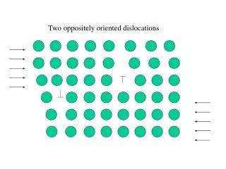
Edge dislocation Interaction between dislocations • Here we only consider elastic interactions between edge dislocations on the same slip plane. • This can lead to Attractive and Repulsive interactions. • To understand these interaction we need to consider Positive and Negative edge dislocations. If a single edge dislocation is present in a material it can be called either positive or negative. If two (or more) dislocations are present on the same slip plane, with the extra half-plane on two different sides of the slip plane, then one of them is positive and the other negative. • The picture (region of attraction and repulsion) gets a little ‘detailed’ if the two dislocations are arbitrarily oriented. [See Stress Fields of Dislocations] Positive edge dislocation Negative edge dislocation ATTRACTION Can come together and cancel one another REPULSION
Dislocations in CCP Crystals • Slip system → <110>, {111} • Perfect dislocations can split into partials (Shockley partials considered first) to reduce their energy • The dissociation into partials leaves a Stacking Fault* between the two partials on the slip plane • The two partials repel each other and want to be as far as possible → but this leads to a larger faulted area (leading to an increase in energy) → depending on the stacking fault energy there will be an equilibrium separation between the partials • The Shockley partial has Burgers vector of the type: (1/6) [211] type. This is an important vector in the CCP crystals, as vectors of this family connect B site to C site and vice-versa. • For a pure edge dislocation in a CCP crystal the ‘extra half-plane’ consists of two atomic planes. The partial dislocations consist of one ‘extra’ atomic plane each (but the Burgers vector of the partial is not perpendicular to the dislocation line- as in the case of the perfect edge dislocation). Figures in coming slides * Will be considered in the topic on 2D defects