Download
1 / 14
190 likes | 725 Views
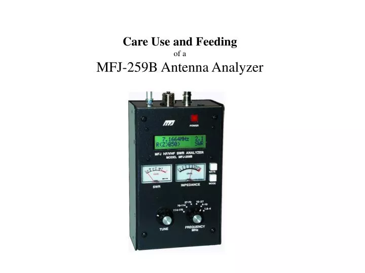
Care Use and Feeding of a MFJ-259B Antenna Analyzer. MFJ-259B Description. Schematic. Block Diagram. Vz= Voltage across the load. Vr= Voltage indicating bridge balance. Vs= Voltage across a series 50-ohm resistor between the RF source and the load. MFJ-259B Operation.

E N D
Care Use and Feeding of a MFJ-259B Antenna Analyzer
Block Diagram Vz= Voltage across the load. Vr= Voltage indicating bridge balance. Vs= Voltage across a series 50-ohm resistor between the RF source and the load.
MFJ-259B Operation Origin - Designed by Tom Rauch - W8JI www.w8ji.com Power - External source Alkaline Batteries Rechargeable Batteries Load - Antenna Connections Frequency Source Other Loads Care and Feeding - Don’t drop it. Don’t get it wet Don’t let it bake in the sun. Be careful of the detector diodes.
Modes of Operation Main mode 1 - Impedance R & X 14.250 MHz 1.1 R= 54 X= 6 SWR Impedance R&X is the initial power-up mode. In this mode, the MFJ-259B LCD (liquid crystal display) shows frequency in MHz, SWR, the resistive part of load impedance (R=), and the reactive part of load impedance (X=). The IMPEDANCE meter displays the complex impedance (Z in ohms), and the SWR meter displays SWR.
Modes of Operation Main mode 2 - Coax Loss 14.250 MHz Coax Loss = 12dB The liquid crystal display(LCD) indicates the test frequency and approximate loss of any 50 ohm coaxial cable, 50 ohm attenuator pad, or 50 ohm transformer or balun (for differential mode current only). In this mode, the 50 ohm device or cable under test must not be connected or terminated by a load resistance at the far end. Main mode 3 - Capacitance 66.120 MHz 263 C= 9pF Xc The LCD shows measurement frequency, capacitive reactance (Xc=) in ohms, capacitance (C=) in picofarads or pF. The Impedance meter indicates reactance in ohms, and the SWR meter displays SWR.
Modes of Operation Main mode 4 - Inductance 66.120 MHz 263 L= 0.633μH XL The digital display indicates measurement frequency, capacitive reactance (Xl=) in ohms, inductance (L=) in microhenries or μH. The Impedance meter indicates reactance in ohms, the SWR meter displays SWR. Main mode 5 - Freq. Counter 66.12 MHz 0.01s Freq. Counter The BNC connector labeled FREQUENCY COUNTER INPUT should connect to the RF sample you want to measure. The sensitivity of this port rangesfrom 10 millivolts at 1.7 MHz to 100 millivolts at 180 MHz. The frequency counter is not design for use below 1 MHz. The “GATE” button controls the gate time of the frequency counter. (.01, .1 or 1 second)
Modes of Operation Advanced Modes - Press and hold both the “Gate” and “Mode” buttons simultaneously until the display shows “Advanced” and then release. Advanced Advanced mode 1 - Impedance 12.004 MHz 1.0 Z= 49 θ= 0º SWR In this mode, the MFJ-259B LCD displays frequency, impedance or Z magnitude (in ohms), and phase angle ( θ ) of impedance. The meters indicate SWR and Impedance. The maximum impedance limit is set at 650 ohms, indicated by the standard display of (Z>650).
Modes of Operation Advanced mode 2 - Return Loss & Reflection Coeff. 12.120 MHz >25 RL=0.3dB ρ=.96 SWR The Return Loss and Reflection Coefficient mode measures and displays return loss in dB and voltage reflection coefficient in percent on the LCD. The meters indicate SWR and impedance. Advanced mode 3 - Distance to Fault 8.3153 MHz 1st DTF X= 0 Select a frequency where the Impedance meter is at the lowest deflection possible and where minimum reactance displayed on the MFJ-259B LCD. Press the “GATE” button. The blinking “1st” on the display will change to “2nd”.
Modes of Operation Distance to Fault continued 25.047 MHz 2nd DTF X= 0 Tune the frequency control to the very next dip in impedance and lowest reactance. Press the “GATE” button again. Dist. To Fault 29.1 ft. x Vf The LCD display will now show the electrical distance to the fault. To convert that to a physical distance, multiply that number by the velocity factor of the cable. If in this example RG-8 coax was used the velocity factor is .66, so the actual distance would be 19.2 ft.
Modes of Operation Advanced mode 4 - Resonance Mode 12.120 MHz 1.0 R= 49 [X= 0] SWR The Resonance Mode displays reactance on the IMPEDANCE meter. In this mode, the MFJ-259B measures frequency, SWR, resistance (R= ), and reactance (X= ). When reactance is zero, the system is said to be resonant. Advanced mode 5 - Match Efficiency (Percent Transmitted Power) 25.167 MHz 4.0 Match = 64% SWR Percentage of transmitted power is yet another way of describing SWR. It is similar to mismatch loss, but SWR data is expressed as a “percentage of transmitted power”.