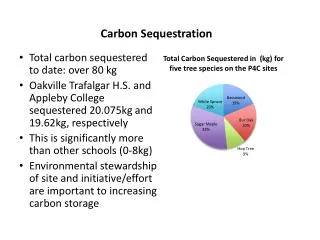
Download
1 / 26
260 likes | 503 Views
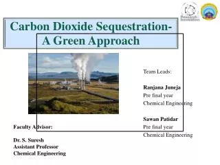
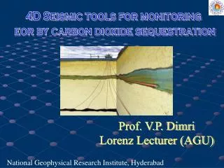
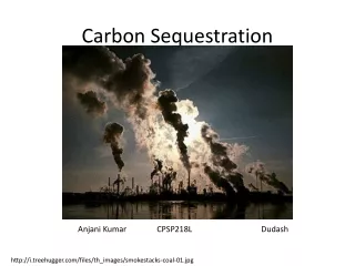
4D Seismic tools for monitoring eor by carbon dioxide sequestration. Prof. V.P. Dimri Lorenz Lecturer (AGU). National Geophysical Research Institute, Hyderabad. Outline of the lecture. Need for EOR CO 2 sequestration Possible potential CO 2 traps 4D Monitoring and EOR Conclusions.

E N D
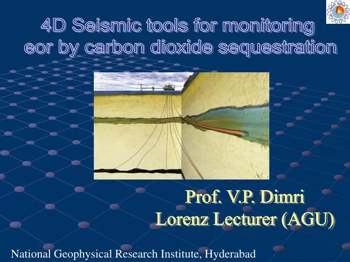
4D Seismic tools for monitoring eor by carbon dioxide sequestration Prof. V.P. Dimri Lorenz Lecturer (AGU) National Geophysical Research Institute, Hyderabad
Outline of the lecture Need for EOR CO2sequestration Possible potential CO2 traps 4D Monitoring and EOR Conclusions
Need for EOR • In India only about 27% of the oil in-place is being produced economically. Recovering these remaining oil and gas resources poses formidable technical and financial challenges. • To wring even the last drop of oil economically from reservoir, lot of research work is going on for enhanced oil recovery (EOR) so that premature abandonment of wells can be checked.
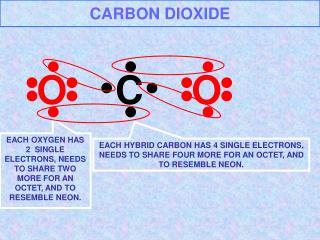
CO2sequestration • Geological sequestration of carbon dioxide is a means of its injection in a suitable geological formation. • Typically below 1 km depth where temperature and pressure are above the critical point for carbon dioxide (31.60C, 7.38MPa).
Characteristics of favourable trapsfor CO2 sequestration Geological reservoirs for safe and long storage for carbon dioxide must meet certain criteria. Some favourable geological traps based on reservoir characteristics such as porosity, permeability, and their affinity for the chemical reactions are discussed below:
Perfect sealing so as to preserve it for long geological time, leakage could lead to environmental disaster • Suitable porosity, permeability and presence of suitable reactants like brine, are some of the criteria of good sequestration sites.
Possible potential CO2 traps There could be several possible traps for efficient CO2 storage, few known traps are discussed here: • Abandoned hydrocarbon reservoirs • Mature (Brown) oil fields • Non-economic coal seams • Shale formations • Basalt formations
1. Abandoned hydrocarbon reservoirs • These are the geological settings in which oil/gas was trapped for long geological time. • These abandoned reservoirs are the best possible locales vacated by the natural oil and gas where carbon dioxide can be stored.
3. These reservoirs have proven capacity of holding natural oil and gas and have good sealing. 4. Under high pressure carbon dioxide turns into liquid (super critical carbon dioxide) and when injected in the reservoir it is trapped below an aquiclude or seal (cap rock).
2. Brown Oil Field: Enhanced Oil Recovery • In a brown field sequestering carbon dioxide becomes an additional advantage because it helps in enhanced oil/gas recovery. • The injected carbon dioxide dissolves in the oil and reduces its viscosity. This is indeed one of the best known commercially viable methods to enhance the secondary recovery from the oil fields.
4D Monitoring • Monitoring of sequestered carbon dioxide is key concern to assure the inhabitants and to policy makers that it has no disastrous / adverse effect on the environment. Monitoring will also demonstrate success/failure of sequestration. • Sequestration can be better planned by monitoring the carbon dioxide storage by finding those pockets of the reservoir which are yet to be flooded with the carbon dioxide.
Indian Case study: Monitoring of thermal front in Balol oil field There is no case study available for any Indian oil field with CO2 injection; however, thermal recovery technique (in-situ combustion) similar to CO2 injection, has been successfully attempted.
A pilot study to monitor the thermal front caused by insitu-combustion in Balol heavy oil field, Cambay basin, was conducted. • Time lapse (4D)seismic data was used for monitoring of the thermal front movement. • Three sets of 3D seismic data acquired in 1 year interval were analyzed.
Case Study Balol oil field lies in the heavy oil belt in the north-western part of the Cambay Basin, India
The reservoir zone is 32 m in thickness and top of the reservoir is at depth of 996 m and bottom of the reservoir lies at 1029 m depth. The porosity of reservoir is in the range of 28-30% and its permeability varies from 8-15 darcy. • At reservoir temperature of 72oC and pressure of 104 kg/cm2, the viscosity of oil varies from 100-450 Centipose and its gravity is about 15.5o API (Heavy Oil). • The primary recovery of viscous and heavy oil from Balol is only 10-12%, hence the pay zone is under thermal EOR process (Insitu Combustion).
Insitu Combustion Process Producer Injector air/water Burning Front Oil Bank light oil
PSTM Stack B M1 M2 Full stack section of migrated data along inline 633 for base (top), monitor 1 (middle) and monitor 2 (bottom).
B Base – Monitor1 (Before 4D analysis) M1 Diff B Base – Monitor1 (After4D analysis) M1 Diff
B Base – Monitor2 (Before 4D analysis) M2 Diff B Base – Monitor2 (After4D analysis) M2 Diff
Thermal front movement near injectors (approx. 50m / year radially). Yellowish colour near injectors shows anomalous regions, which represents thermal front movement.
Inversion results Constant time slices of inverted P-impedance are in a 10 ms window centered at 900ms for baseline, monitor1 and monitor2 surveys.
We see a drop in impedance from baseline to first monitor survey near all the injectors. Low impedance anomalies near the injector wells 145, 147, 153 and 162 are identifiable in these figures and are indicative of the effect of combustion.
Conclusions • Carbon dioxide injection serves two purposes, one to reduce CO2 from atmosphere and other to enhance oil recovery from brown oil fields. • Geological sequestration of carbon dioxide to reduce global warming is an active area of research. • NGRI has taken a lead role to launch a project on Deccan Volcanic Province with financial support of DST, Govt. of India, as a pilot project.