Download

1 / 97
1.05k likes | 1.29k Views
Locosto DRP. David-wang@ti.com. Locosto DRP. DRP2.0 Overview Receiver LO, Synthesis and Transmitter DCXO DRP LDOs and Power Management APC AGC Clock management Script Processor and SRM DRP Wrapper DRP Timings. Digital RF Processor Overview. DRP summary.

E N D
Locosto DRP David-wang@ti.com Locosto RF
Locosto DRP DRP2.0 Overview Receiver LO, Synthesis and Transmitter DCXO DRP LDOs and Power Management APC AGC Clock management Script Processor and SRM DRP Wrapper DRP Timings Locosto RF
Digital RF Processor Overview Locosto RF
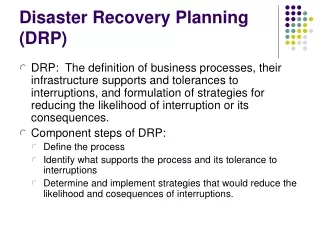
DRP summary • Locosto DRP is a fully integrated 4 band GPS/GPRS transmitter • The DRP technology enables software definable radio (SDR) • This technology allows cost effective integration of the radio function • TI Digital Radio Processor (DRP) is a complete Radio subsystem including: • Frequency synthesizer: ADPLL • Digitally Controlled Oscillator (DCO) • Digital loop filter and phase detector • Reduced Lock Time (Loop BW adaptation) • Transmitter: • Based on ADPLL • Digitally self-calibrated two-point modulation • Receiver: • Configurable to zero IF or near zero IF • MTDSM (multi-tap-direct-sampling-mixer) • LO generated by ADPLL • Digital Interface with Baseband • Power management and start up engine (On-chip Bandgap + LDOs) • Clock management (DCXO) with clock noise reduction by retiming • Software script processor for transceiver sequencing and calibration Locosto RF
Radio Interface Block Diagram ADPLL ABE AFE Locosto RF
Digital RF Processor Receiver Locosto RF
DRP XTAL VR1 VR2 VCORE PURX F32 SLEEPX (1.35V) (2.78V) (2.78V) (BGAP & LDOX) DIG ANA T DCXO S MEM DMUX T AMPLITUDE DCXOIF D IDAC PDET ADC SUS RFTST JTAGIF CONTROL SCR XTAL_CTL SRM OSC FREF VBUF LDOX SDM 1.4V, 5mA RXBUF TXBUF SCRMEM ARXCWIF FREF DTX ALOTX FLT BGAP MEM /4 PPA_LB GSM/ CTL EGSM TEMPSENS LDOOSC INTPL BUFFER 1.4V, 30mA /2 DCS/ PPA_HB LOCOSTO PCS DLO WRAPPER PHASE LF from DTX SAM BRIDGE MEM O DCOIF DCO /2 /2 RAM CAL C USD P TDC TSP CKM CKRET CKV CKR (CKRET CKM PVL) 1.4V, 30mA MEM BSP LDORF DRX AFE ABE SW MEM LDOA IREF GEN ARXCW FCU 1.4V, 30mA I/Q LUT PRE DACs ATST MTDSM C ADC D FBUF REF A LUT B B B DCEST I-Channel POST I PCS H H H H A X A SDM CTA SCF I N C DCS T M L F 1 C F S C DCU F F PCU E M S E I O C B R B Z Q Q B R C R EGSM L R L P I L SDM A CTA X H SCF A I N C GSM T M L Q-Channel ADC C FBUF Note: The DRX path is D REF time interleaved A RX Location in DRP2 system Locosto RF
RX blocks IREFGEN Locosto RF
Digital RF Processor LO & Synthesis & Transmitter Locosto RF
DRP2.0 SYNTHESIZER/TX BLOCK DIAGRAM I TX LB VCO IF filter 90o PFD TX HB VCO IF Q MAIN VCO 1 @ 3.37 GHz MAIN VCO 2 @ 3.80 GHz 26 MHz Main Loop Filter M PAD toward RX mixers LO R PFD L N MAIN PLL ADPLL Locosto RF
Frequency synthesizer • Based on an All-Digital PLL (ADPLL) • Digitally Controlled Oscillator (DCO) at 1.8 GHz as the RF frequency source • The frequency setting uses FCW (fixed-point Frequency Command Word) • The phase correction mechanism in 2 steps: • The integer part of the phase detector computes the phase difference between the DCO output clock and the retimed reference clock (reference clock resynchronized with the DCO clock) • The fractional phase error between the reference and DCO output clocks is estimated by the TDC (Time to Digital Converter) and added to the integer phase error.. Locosto RF
All-Digital PLL (ADPLL) block diagram Synchronous digital phase domains (key idea of the ADPLL to avoid metastability problems in TDC and reduce noise) Locosto RF
All-Digital PLL (ADPLL) block diagram Locosto RF
Gear-Shifting of PLL Bandwidth • Progressive reduction of ADPLL loop bandwidth while the loop is settling • Lock time max = 170 usec (RX) and 240usec (TX) Locosto RF
ADPLL BUILDING BLOCKS (1/5) • Digitally-Controlled Oscillator (DCO) Time-to-Digital Converter (TDC) Digital Loop Filter (LF) All-Digital PLL (ADPLL) ADPLL Wideband Frequency Modulation Locosto RF
DCO: varactor banks overview Locosto RF
ADPLL BUILDING BLOCKS (2/5) Digitally-Controlled Oscillator (DCO) • Time-to-Digital Converter (TDC) Digital Loop Filter (LF) All-Digital PLL (ADPLL) ADPLL Wideband Frequency Modulation Locosto RF
Time-to-digital Converter (TDC) • Estimates the fractional Phase Error • Quantized phase detector with resolution of <20 ps Locosto RF
ADPLL BUILDING BLOCKS (3/5) Digitally-Controlled Oscillator (DCO) Time-to-Digital Converter (TDC) • Digital Loop Filter (LF) All-Digital PLL (ADPLL) ADPLL Wideband Frequency Modulation Locosto RF
Digital loop filters • 4th order digital IIR loop filter to suppress the frequency reference and TDC quantization noise • Unconditionally stable IIR filters Single-pole IIR stage: Locosto RF
ADPLL BUILDING BLOCKS (4/5) Digitally-Controlled Oscillator (DCO) Time-to-Digital Converter (TDC) Digital Loop Filter (LF) • All-Digital PLL (ADPLL) ADPLL Wideband Frequency Modulation Locosto RF
All-Digital PLL (ADPLL) • Type-II 6th-order PLL loop • Reduced Lock Time (Loop BW adaptation) • Synchronous digital phase domains (key idea of the ADPLL to avoid metastability problems in TDC and reduce noise) Locosto RF
ADPLL BUILDING BLOCKS (5/5) Digitally-Controlled Oscillator (DCO) Time-to-Digital Converter (TDC) Digital Loop Filter (LF) All-Digital PLL (ADPLL) • ADPLL Wideband Frequency Modulation Locosto RF
ADPLL with GMSK Modulation • Two-point modulation • Direct feedforward path : y[k] directly drives the DCO • Compensating path: y[k] added to the channel FCW Locosto RF
OTHER RF TX BUILDING BLOCK • Digitally-Controlled Power Amplifier Locosto RF
Digitally-Controlled Power Amplifier • Class-E PA with MOS transistor switches The DPA can be thought of as an RF DAC, where “A” is RF “amplitude” • Array of unit-weighted MOS switches, that can be programmed through API to achieve the TX desired output level (up to +8dBm) Locosto RF
Digital RF Processor DCXO Locosto RF
0.1ppm freq accuracy required (GSM/WCDMA) Freq Sync Signal DCXO Synthesizer 26MHz REFCLK Freq Sync Signal 0 0 ADC 90 90 I Digital Baseband ADC LNA Q T/R SW PPA DAC I PA TX Signal < 0.1ppm Freq Error DAC Q RF+ABB+DBB AFC Loop in GSM/EDGE Network Locosto RF
VCXO vs. DCXO VDD_HI_Volt Digital BaseBand VCTRL AFC DAC AFC XI VCXO Trim GND RF+ABB+DBB Digital BaseBand AFC XI DCXO GND RF+ABB+DBB DCXO Locosto RF
DRP - DCXO overview • Low phase noise clock reference for RF clock synthesis • Large tuning range : 10 bits digital codeword for coarse tuning • Accurate frequency : 14 bits digital codeword for fine tuning • Oscillation amplitude control to limit crystal power drive • Oscillation amplitude detection to tune startup time • State machine for startup tuning procedure Locosto RF
DCXO System Startup State VR2 Machine FREF (CKXA) BGAP LDOX IDAC Amplitude Control Thresh1 IIR > Time Thresh1 Measurer OSC Peak 1 FREF ADC IIR Time – Time C Detect 2 1 R Time Expected IIR > 13:4 Thresh2 /16 Thresh2 Unity 1 Mult1 W Mult2 IDAC O INT O SDM DITHER 1 State Machine 4 : F32 : : XTAL_CONTROL Amplitude Control Block Locosto RF
Coarse Frequency Control Coarse Frequency Adjustment (CFA) capacitor consists of: • Fixed capacitor of size 168 units • Modified-binary array with 10-bit control, with individual weights of 1, 2, 3, 6, 12, 24, 48, 96, 192 and special capacitor of ~200 units respectively • CFA calibration is needed to obtain initial CFA value that gives optimal tuning range using Fine Frequency Adjustment only Locosto RF
Fine Frequency Adjustment • Fine Frequency Adjustment (FFA) is controlled via 14-bit codeword • The physical capacitor array consist of 1024 capacitors. • Capacitor array is tapered, with sizes ranging from ~30fF to 100fF. • Tapering creates linear transfer function between codeword and the frequency • Additional 4 bits of frequency resolution are obtained via digital Sigma-Delta modulation of an array element Locosto RF
Fine Frequency Adjustment (cont.) Example: 14-bit codeword, codeword 0000000010_0111, or 2 and 7/16th correspond to turning on 2 capacitor array elements, and turning on another capacitor element, 7 out of every 16 FREF clocks (on average) • Typical frequency resolution of the FFA is 0.002 to 0.003ppm/LSB • This may vary substantially with the crystal and CFA value chosen during calibration Locosto RF
Amplitude Control in DCXO • High amplitude of oscillation in a DCXO produces superior phase noise • High amplitude of oscillation may cause power drive of crystal to be exceeded causing damage to the unit • The Amplitude is directly affected by the current • The Amplitude is also heavily influenced by the changes in tuning capacitance (FFA) Locosto RF
DCXO Startup • DCXO startup and wakeup require special hardware, since FREF clock is not available until DCXO becomes fully operational and therefore the DSP, the Script Processor and the FLASH memory are inaccessible • DCXO startup is clocked by the clock from the 32kHz crystal • All three IDAC codewords go to their default values of • Numerator = 128 • Denominator + Fraction + Fixed = 0 + .0 +128 Locosto RF
DCXO Startup • Startup sequence consists of three phases • Quick Charge: IDAC current is set to 3X nominal value of IDAC current. This is done in order to guarantee that the oscillations will begin. The output of the 5-bit ADC is monitored for the crossing of first programmable threshold (thr1). On the second 32 kHz clock cycle after the crossing of the thr1 is detected, Phase 1 ends. • Linear Ramp: IDAC current is set to X nominal value of IDAC. The output of the ADC is monitored for crossing of the second programmable threshold (thr2). • Final Settling : New value for IDACN is set using formula Locosto RF
DCXO Startup (cont.) Locosto RF
Digital RF Processor Power Management Locosto RF
PCB-Level Overview VCore VR1 DBB, APC… DRP VR2 Locosto Triton Locosto RF
DRP-Triton Interface 1.4V , 5mA1 mF external capLow Noise at low frequencies < 10mA To DCXO VR2=2.78V 1 mF LDOX VREXTH 10 mF To DRP 0.9V Internal, Trimmed BGAP VREF LoCosto Triton VREF 1.1V to 1.8V, 30mA4.7 mF external capLow Noise at high frequencies 470 nF To DCO 4.7 mF LDOOSC 1.1V to 1.8V , 30mA1 mF external capLow Cost-Area < 70mA VR1=2.78V To RF 1 mF LDORF VRMMC 10 mF 1.1V to1.8V , 30mA1 mF external capLow Cost-Area To ABB 1 mF LDOA VREF1 To DRP IREF VREXTL To DRP 45 kW Locosto RF
VREF BGAPCore VBUF 360 kW 40 kW 470 nF 32.5 pF VREF1 • VREF pin has high impedance in nature • Watch for nearby PWB routings • Star connection from VREF • VREF has priority on PWB • VREF1 is secondary VREF pad, ball 0.9V Internal, Trimmed Locosto RF
IREF current mirror VREF1 IREF pad, ball AMP 45 kW • IREF pin has high impedance in nature • Watch for nearby PWB routings Locosto RF
LDOs / VREF / IREF specifications Locosto RF
LDO Key Specifications/Care-about • Cost -External capacitor size -Silicon area • Nominal voltage - 1.4 V after trim • Iload,max,avg - 30 mA except LDOX of 5 mA • Active and passive disable • PSRR relaxed (Since VR1 and VR2 are regulated) - Reduced LDO bandwidth - Better noise performance • Turn-on time - (1% settling) < 150 ms - Measured: < 80 ms for all LDOs in MS4 data Locosto RF
LDO Noise Measurements • Currently LDOs provide satisfactory noise performance according to transceiver parametric data • All LDOs have similar noise performance • LDOOSC, LDORF and LDOA have better low-frequency noise than spec. • Plan to unify LDO design for future generations • Plan to further reduce power/ground domains for future generations, which also further reduces cost Locosto RF
Power Management DRP2 needs 3 external power supplies: • VCORE: DRP Core digital supply: 1.3 V • VCORE is connected to DBB core voltage VDD_CORE. • Total consumption on this power domain (DRP + DBB) is 140 mA (DRP ~35mA). • This power domain must be present before all other DRP mega module supplies. • Low voltage mode: to reduce leakage during sleep mode (voltage reduced to 1.05V) • VR1: Pre-regulated input to LDO_OSC,LDO_A and LDO_RF DRP embedded LDOs. The required supply is 60 mA at 2.8V. • This power domain is isolated from the VCORE allowing VR1 switch off while keeping VCORE active or in low consumption mode. • VR2: Pre-regulated input to LDO_X DRP embedded LDO. • The required supply is 10 mA at 2.8V. This power domain is isolated from the VCORE allowing VR2 switch off while keeping VCORE active or in low consumption mode Locosto RF
Power Management sequencing • VCORE is provided first at start-up • Then VR2 (DCXO) is provided by Triton, then VR1 for other RF blocks. • VCORE and VR2 sequencing is controlled by Triton FSM. • VR1 is switch ON/OFF is controlled by SW. Locosto RF
Digital RF Processor APC Locosto RF
APC in Wrapper - Triton Interface < 10mA LOCOSTO WRAPPER VR2=2.8V VREXTH DRP 10 mF LDOA LDOOSC LDOX LDORF BG VREF IREF Triton < 70mA VR1=2.8V VRMMC 10 mF 100nF APC_LDO_FILTER 1.4V LDO Band-Gap 100nF APC_VREF 0.9V APC VDO APC Ctrl APC OUT APC DAC VREXTL VCORE=1.3V Locosto RF