Download
1 / 12
120 likes | 231 Views
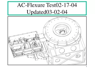
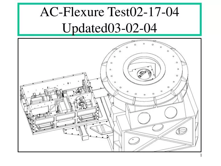
AC-Flexure Test02-17-04 Updated03-02-04. Moment Load about E-W Axis-1. W into page. XY Stage. Box. S. N. 20 lbs +/-5%. George. Brace 2 Plcs. AO-Spool. Result of 20 lbs load: .005 inch flexure at point of application of load. Pivot Point. E. Moment Load about E-W Axis-2.

E N D
Moment Load about E-W Axis-1 W into page XY Stage Box S N 20 lbs +/-5% George Brace 2 Plcs AO-Spool Result of 20 lbs load: .005 inch flexure at point of application of load Pivot Point E
Moment Load about E-W Axis-2 • Results: • Applied force tends to rotate Structure about pivot point marked in sketch (prev. slide) • .005 inch Flexure seen will have contributions from Box , XY stage and George Mount • Any looseness in XY stage will contribute to flexure measured • We see .0025 inch by pushing/pulling just on XY stage in E-W direction (Stage Stop?) • Results Interpretation and Suggestions: • Do a flexure test around E-W axis ( going North and South) • .005 flexure translates into an angle at POM of ~ 36arc-sec • Using Zemax, what does a 36 arc-sec tilt at the POM mean? (Doug) • Examine XY stage for looseness (anti-backlash) • Add Braces to George Mount.(see previous slide) • Comments: • Adding Braces to the George Mount means connecting the George Mount to the AO-Spool with tubular material on two sides (see slide). This will stiffen up the George Mount if it is not stiff enough in this plane. It could be tried out by just clamping these rectangular tubes in place and if found to reduce the flexure substantially, permanently bolted to both the AO Spool and the George Mount. We could also rebuild the George Mount, but choose Steel for the Material instead of Alu 6061. • But the preference would be to add the tubular stiffeners, since the XY stage is made from Aluminum 6061-T6, to avoid thermal mismatch between George and XY stage.
Moment Load about parallel to optical axis-1 W into page XY Stage Box S N George 2nd Pt of Application of 20 lbs force Push/Pull 1nd Pt of Application, on George Push/Pull Rot- Axis Optical Axis E
Moment Load about parallel to optical axis-2 • Results: • Structure is stiffer in this axis then previous axis by factor of ~2 (see update at end of ppt) • For 1st Pt of appl.: 20 lbs force: .0005 inch both directions (F on George);see FEA-1 • For 2nd Pt of appl.: 20 lbs force; .0025 inch both directions (F on Box);see FEA-2 • Results Interpretation: • The lever arm ratio between 1st and 2nd Pt of application of the force is about 2:1 with respect to the rotation axis. Treating the structure as a cantilevered arm, the deflection is proportional to the cube of the distance from pivot. We would therefore expect a deflection of (2)^3, or 8 * .0005=.004. We measured .0025, somewhat less, which may be because we have unequal moments of inertia in the structures involved. • We also pushed/pulled on the XY stage in a N-S direction and observed a movement of .0025/.003. This would indicate looseness in the XY stage; could be a problem with the anti-backlash • Suggestions: • Contact XY stage Vendor for info on impact on specs for temperature changes (see site) http://www.neat.com/techinfo/thermal.asp • Using Zemax, evaluate a rotation of 18 arc-sec at location of POM • Disassemble Acquisition Camera; inspect all optical mounts, including POM, for any looseness in the optical mounts; check all bolts; check POM assembly for any looseness • Add missing fasteners to Acquisition assembly (I noticed some are missing) George,Lars
George Mount FEA-1 Did Simulation with 20 lbs as was done in Field at Summit: Result: max deflection .00032 inch as compared to .0005 on summit. The difference is probably due to constraining the bolting surface rather than just the bolt holes 20 lbs Force in -z-direction
George Mount FEA-2 Worst Case: Loaded with 130 lbs which includes the XY stage, Acquisition Camera and Gravity. This is the equivalent of having the telescope horizontal. This indicates that the George Mount is not responsible for the .0025 inch movement we are seeing when applying 20 lbs as was done while on the summit.
Summary: • The flexure tests mirror the Finite Element Analysis done of the George Mount(see Fea’s) • The George Mount is weaker in one plane than another at 90 degrees by factor of 2(not true) • Weakness could be remedied by adding braces as explained. • To be certain the movements we measured are responsible for the 3 arc-sec tilt observed by David, we would need a Zemax ray-trace to verify. • In the absence of a ray-trace, it is difficult to tell if our measured movements can explain the tilt. There is still the possibility of something loose inside the Acquisition Camera. So far, we have not done any checking on the inside of Acquisition Camera. • We do not have conclusive evidence that the observed flexures are responsible for the tilt measured by David. • The XY stage is made from Aluminum Monolith. The lead-screw is made from Stainless. For the test under consideration, the are no differential changes we need to account for. This is because both structures interfacing to the XY stage are also made from Aluminum and we are not moving the XY stage. For further info on this subject please look up http://www.neat.com/techinfo/thermal.asp • Doug: Can you think of any further steps we should take to get to the bottom of this?
Update 02-24-04 • A subsequent FEA of the George Mount using exactly the same boundary conditions as were used for the 2 that are pictured in the .ppt revealed that the George Mount has almost identical stiffness in planes 90 degrees apart from each other. • Therefore, the statement that the George Mount has different stiffness in planes at 90 degrees to each other is not in agreement what was found by doing an FEA. Because the FEA’s were done with identical Mesh, Boundary Conditions and Restraints, and only the direction of the Load and Gravity was changed, this is a result that can be trusted. • It is NOT the George Mount that is responsible for the indicator readings to show values that differ by a factor of 2. Rather, it is the the Acquisition Box that is the contributing factor. I am assuming here that the XY stage behaves the same when loads are applied to the Acquisition Box structure. • This also makes sense intuitively, because when we took readings on the Box we loaded the structure in quite different ways. We got the .005 inch reading when applying the load perpendicular to a plane of the base plate , and the .0025 inch reading when we loaded the edge of the base plate. • This is not to say that adding the braces would not improve the situation. If the braces would cut the deflection of the George Mount in half, the deflection at the end of the Acquisition Box would be cut in half. The question that needs to be answered is: Will this fix the problem observed when moving the telescope
Conclusions & Next Steps • Flexure tests taken on the George Mount and FEA runs show sufficient agreement. Maximum deflections in the George Mount was found to be no more than about .002 inch measured in planes that carry the load. The two worst cases were modeled. • We may want to check the XY stage. We pushed/pulled the stage and found movement of approximately .0025 inch in either direction when we applied a force of 20 lbs. Even if the motor break is on, the backlash between nut and lead-screw will show up. Part of the force will go into overcoming friction, the rest of the force is translation of the stage itself to bottom out the screw against the nut. We also increased the force on the XY stage to about 50-70 lbs and found that the motion increased to ~ .010 inch. To check the XY stage and to fix it, we will have no other choice but to remove it from the assembly. • The stiffness of the Acquisition Box is harder to judge from the measurements taken. The 3 tiered assembly of George Mount, XY stage and Acquisition Box each contribute to a measurement taken at the Acquisition Box. Since this is a “boxed” assembly, it is intuitively very stiff. The fact that some bolts in the side walls were missing and some were not sufficiently tight may have given us unreliable readings. The FEA simulation that was done with the Acquisition Box showed no deflections greater than .001 inch. As with the George Mount, two worst cases were modeled. • To gain an understanding of how these deflections/tilts affect image motion we probably would need to put this into a ray-trace program. • There is still the possibility of something “loose” inside the Acquisition Box itself.It could also be the POM (Pick Off Mirror). To verify this while the Acquisition Box is on the telescope is almost impossible because of access problems. If the image motion problem persists, and after we ascertained that flexures/tilts we found are not at fault, we will need to remove the units from the telescope to troubleshoot. This may take 2-3 days plus we may have to send the stage back to the factory for readjustment. • A question that keeps surfacing is whether we experienced this image motion when the Relay Structure was used rather than the George Mount. Maybe the trouble-log could shed light on this. • The measurements taken on the XY stage and the George Mount in the E-W direction yielded .0025 inch (XY stage vs.0005 inch (George Mount). This alone would indicate that we should take a look at the XY stage’s anti-backlash feature.