Download
1 / 68
680 likes | 771 Views
NIRSPEC-IFU Management Meeting. LAM – ESA – ASD 15/10/04. Introduction. Meeting called by ESA and ASD Request to LAM to change implementation approach Demonstrate IFU can be delivered in specs Demonstrate IFU can be delivered in time Capitalize on on-going development

E N D
NIRSPEC-IFU Management Meeting LAM – ESA – ASD 15/10/04
Introduction • Meeting called by ESA and ASD • Request to LAM to change implementation approach • Demonstrate IFU can be delivered in specs • Demonstrate IFU can be delivered in time • Capitalize on on-going development • Redefine industrial team • Design and development approach
NIRSPEC IFU Development History I. • LAM has demonstrated that integral field spectroscopy is required for NIRSPEC • 3D approach (,,λ) is a very powerful science tool • Used on ground based observatories • Included in the NGST “Design Reference Mission” as optional instrument following our studies • LAM has developed IFU concept under ESA contracts, over more than 6 years • Needed to develop the technology and qualify for space • Today: intense LAM R&D has led to the space qualification of a revolutionary new technique, modulo a few remaining items • A unique worldwide know-how • LAM key partner for SNAP, TMT (30m), ESO-ELT, OPTICON • IFU on NIRSPEC: a very visible item on-board JWST
4 1 3 2 Slicer Principle How to rearrange 2D field to enter spectrograph slit: • Field divided by slicing mirrors in subfields telescope pupil on the pupil mirrors • Aligned pupil mirrors • Sub-field imaged along an entrance slit Courtesy: JR Allington Smith
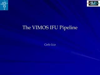
IFU techniques: implemented and work on 4-8m ground based telescopes • Several IFUs in operation • ESO-VLT, VIMOS • Build by LAM • Gemini • WHT • CFHT λ 1/8th VIMOS IFU Spectra
Key “historical” points • LAM has created a unique robust IFU optical design • No competitor worldwide in visible - NIR • LAM has been an essential contributor to NIRSPEC design. • Optical concept from LAM • Has helped ASD to focus on proper design analysis (Phase A “crisis”) • LAM has been a key partner for ASD to win NIRSPEC contract • Essential expertise at LAM not present at ASD • Excellent partnership over 6 years
NIRSPEC & IFU Development steps • IFMOS: 1998-1999 • ESA-LAM contract • ASD sub-contractor • Payload Study: 1998-1999 • ESA-ASD contract • LAM sub-contractor • IFMOS2: 1999-2001 • ESA-ASD contract • LAM sub-contractor • NIRSPEC pre-Phase A: 1999-2000 • LAM contract • ESA-ASD sub-contractor • NIRSPEC Phase A: 2000-2002 • ESA-ASD contract • LAM sub-contractor • NIRSPEC pre-Phase B: 2002-2004 • ESA-ASD contract • LAM sub-contractor • NIRSPEC-IFU prototype: 2002-2004 • ESA-LAM contract
What did we secure ? • A unique optical design • Demonstrated to be valid by prototype image quality √ • A robust implementation concept inside NIRSPEC √ • No moving parts, Input FOV selected by MSA • A unique manufacturing technology √ • Micro-optical components of very high quality: Thin glass slices, optical bounding • Successful R&D with Cybernetix • A prototype has been build • Complex optical system produces outstanding images, well within specs √ • 2D to 1D demonstrated √ • Individual components survive vibration tests √ • Overall opto-mechanical concept √ • Optical bounding √ • Unrestricted vibration tests √ • What if MSA fails ??? √ • IFU identified as a backup option
What are we missing ? • System approach • Simulated dynamic opto-mechanical model • Demonstrated vibration test survival • Need to apply simulation results to notch appropriately • Prototype was vibrated full-on without adequate notching ! • Nevertheless, very limited breakage • Lesson from prototype vibration test very valuable • Increment toward full success is small compared to existing development successes • A lot has been done • Remaining validation work compatible with phase B
Why the harsh action from ASD and ESA ? • ESA-ASD need 100% proof of success • Understandable managerial goal • Late delivery of prototype • But acknowledge successes on a complex development not so obvious to develop at start • Compare to other risky components like MSA: IFU in pretty good shape ! • Vibration test results are interpreted negatively • But no acknowledgement of successes • LAM is not industry • We tell you everything ! • We are motivated because we are users • Capabilities to react on immediate notice not so easy, but we are significantly cheaper • Negative comments about CNRS are irrelevant • Knowing us for 6 years, Astrium never raised the issue nor asked for a management meeting to discuss contractual arrangements • Why does it come so late ? • Ample time to iterate on development approach if not satisfactory • Full cooperation spirit since 6 years ! • New project managers
ESA ASTRIUM concerns • ESA and Astrium presentation
Technical Baseline I. Start from prototype
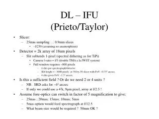
IFU optical design: out of reach of industry, unique to LAM Slicer unit optical design for the IFS Slit Mirrors Pupil mirrors Slicer mirror Entrance Pupil
Slicer unit optical design for the IFS • Radius of curvature: ~ 150 mm • Tilt in Y: +/- 3.7° • Tilt in X: from 3.3 to 9° • Thickness: 900 µm • Width: 27 mm
Slicer unit optical design for the IFS: pupil mirror 300µm • Pupil mirror pitch: 2.754 mm • Pupil oversizing in spectrograph: <2 • Tilt Y: +/- 3.7° • Tilt X: 3.65° –> 6° • Curvature Radius: ~24.5mm
Slicer unit optical design for the IFS: slit mirror 500µm • Pitch: 2.754 mm • Curv. radius: 26.5 mm • Tilt Y: 0° • Tilt X: 6.5°
Image Slicer : 2nd design After sine sweep tests and static load FEM analysis , a new design was implemented to ensure higher rigidity
Pupil mirror array Dummy Stack Slit mirror array Active Stack Heel Stacksupport Thrust cylinders Substructure Steeringmirror Main structure Design Overview
Clamp Slicer Stack 2 Dummy slices 10 Active slices 18 dummy slices Clamps
Crosstalk +/-40µm relative for a specification of +/- 120µm
Slits separation Plots of the intensity profiles in the regions between the pseudo-slits. Lowest contour in the plots corresponds roughly to ~1% of the peak intensity (50 for a peak intensity of ~3000).
Image Slicer : Modal Analysis From Sine sweeps (3 axis), we fit with a model of n SDOF : We get the main proper frequencies of the specimen, and associated damping or quality factor (Q)
Image Slicer : SDOF parameters (F,Q) are input for NASTRAN dynamic FEM Model :
Lessons Learned from the prototype development • LAM Team R&T development spirit while the contract was more flight hardware delivery oriented ( ESA did not refocus during the study) • LAM experience in structural dynamic analysis not sufficient • No internal review conducted before final and critical vibration tests and report delivery • Estimates of delays not properly handled • LAM needs external support • But the prototype is finished and the core technology is validated
How to proceed for the NIRSPEC-IFU development • Need of phase B/C/D industrial management type • Need support for dynamical analysis study • LAM concentrates on optical development and tests • Refocusing on our core activities
Image Slicer : post-vibration Expertise • Inspection • Flakes are located at contact area with metallic (invar) stops • Fretting corrosion marks at these locations Optical parts have moved No non-emerging cracks • Analysis • Geometry of contact area is not compatible with glass/metal contact criteria • Location of stops is not optimized to loads repartition • QSL dimensioning is not appropriate, end despite notching, as 5 sigmas levels found • Solutions • Improvement of the contact points between Zerodur and Invar • Avoid contact points near the edges of the Zerodur part • Compute the required forces to maintain the optics, then increase the force of springs
Image Slicer : support solutions • Solutions • Recompute force applied • Not strong enough • Increase by x2-3 • Groove in metal • Beveled edge on glass • Clamp on back support • Fused silica instead of zerodur ? • Less brittle • Glass to metal • Soft material • Gold • Fixed spherical contact • Self adjusting spherical washer
Image Slicer : Non linear analysis • Lateral breakouts on Zerodur pedestals can only be modelised with nonlinear elements (slipping and gap elements). • This kind of sophisticated model can’t be used for classical random FEM analysis (with NASTRAN) • non linear temporal analysis of deflections and stresses is under development.
Foreseen Wrenching tests 1st set up 2nd set up • We have already performed a wrenching test, 3 time with the same specimen. We have obtained 3 time the same value (18N) • We are working (in advance of phase) on a statistic study (33 specimen) to determine the optical bond strength. • We are establishing a test plan and designing the tools. Translation Adjustable mass Zerodur main support mirror Stainless Steel ball(thrust)
Technical Baseline II. Proposed design
120 mm 64 mm 207mm Overview
Entrance beam Exit beam Pupil mirror Slit mirror Slicer stack
Invar (frame and optical support) Optical elements in Zerodur Opto-mechanical mount TBD Kinematics mount TBD
Assembly philosophy • Frame designed to support 3 sub-assemblies • Each sub-assembly supporting optical elements can be set-up separately • The interfaces are designed to guarantee a good positioning
Weight Weight: Mechanics 810 gr baffling 250 gr optics 70 gr thermal sensors 12 gr Total 1212gr
Industrial Team • Assume LAM not prime • ESA and ASD critical • Goal oriented: fly the IFU on JWST • Build consortium with relevant industries • Knowledgeable about IFU technology • Long track record on space experiments Does not exist today Be pragmatic • Involve Cybernetix for responsibility in IFU delivery and performances around their core technical expertise • Involve ASF for key support