Download
1 / 26
260 likes | 365 Views
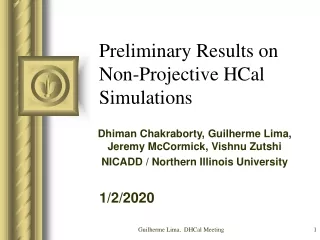
Semi Digital HCAL Data analysis results. Robert Kieffer Institut de Physique Nucléaire de Lyon kieffer@ipnl.in2p3.fr. Outline. Test beam periods summary. Small chambers studies Large chambers studies Power pulsing Conclusions. Test beam periods summary.

E N D
Semi Digital HCALData analysis results Robert Kieffer Institut de Physique Nucléaire de Lyon kieffer@ipnl.in2p3.fr
Outline • Test beam periods summary. • Small chambers studies • Large chambers studies • Power pulsing • Conclusions
Test beam periods summary • More than 1400 kEvts taken using pion beams • A lot of complementary cosmic data taken at lab.
Tracking analysis principle (cm) (cm) Large chamber Offline reconstruction: • Clustering in chambers • Track fitting in small setup • Alignment (σ±1 cm) • Projection in large chamber. • Check if there is a cluster. • Compute local efficiency Small Setup (cm) (cm) XY alignment ( small setup Vs Large chamber) Distance: point réel /point attendu (cm)
Small chambers studies using HARDROC1
Time selection on Small chambers data All events (Sig+Noise) Actual spill Previous spill Trigger noise (ms) Out of time (Noise) Events in time (Signal) Scintillators coincidence was used to trig the readout
High voltage scan Results obtained using tracking Resistivecoatingcomparison: • Threshold: 120 fC • Plateau: 7.2 à 8kV => Efficiency: 90 to 98% • Best working point 7.4kV for Licron and Statguard. • Lower the multiplicityBest the spatial resolution Resistivecoatingcomparison:
Angle scan Results obtained using tracking We didn’t see any angle effect on detection efficiency
Performance maps in small chambers Results obtained using tracking Efficiency Map (1cmbinning) MultiplicityMap (0.33cm binning to seeinterpadeffect) PAD Linked cells causes higher multiplicity
Photogrammetric spots for alignment Eudet Telescope Table XY with 4 GRPCs Tracking with EUDET pixel telescope Beam
Interpad efficiency Black (Trigger): spatial prediction of hits in GRPC, from EuTel. Red : matched digital hits (EuTel + GRPC) Efficiency: Red/Black No efficiency loss on interpads (500 μm) Tracking resolution σ±10μm
Large protypestudiesusing HARDROC 2 1m2 Cassette 144 ASICs = 9216 channels/1m2 Beam
Beam profile in a Large chamber (1m2) Result obtained using time selection only Verylow noise contamination.
Efficiency homgeneity Vs HV scan Results obtained using tracking HV scan on 3 differents areas. Statguard coated chamber. Top-Right Top-Center Down-Left DIF6 DIF10 DIF9
Efficiency homogeneity studies • HV: 7.5 kV • Threshold: 144 DAC • Position scan area limited by the movable table. Results obtained using time selection only 1m2 GRPC map
Multiplicity homogeneity studies • HV: 7.5 kV • Threshold: 144 DAC • Multiplicity highly related to threshold level but quite homogeneous. Results obtained using time selection only Preliminary 1m2 GRPC map
Power Pulsing Test Beam Beam conditions: 80GeV @ High Rate Aim: PowerPulsing tests using B field. 32x48 cm2 GRPC Beam B field Beam 3T Magnet
B field effect on chamber efficiency No Power Pulsing B field has no impact on efficiency. Preliminary Results obtained using time selection only
B field effect on chamber multiplicity Preliminary No Power Pulsing Results obtained using time selection only B fieldincreasea bit the multiplicity.
Principle of power pulsing Power On Period: 10ms (100 Hz) DutyCycle: 2/10 2 ms Data taking Δt Enable Acquisition Waking time 100 μs Trigger for chip readout Trigger Pulse Generator 2ms/10ms Power On Injecting on falling edge through a 2pC build in capacitor ASU Scintillator Coincidence & Trigger DIF « In Spill » Signal Enabling Power Pulsing: consumptiongoesfrom 2A to 0.7A Veto From Acquisition Busy
Timing of power pulsing Trigger taken in two consecutive power-cycles (10ms) One cycle without trigger (20ms) Two cycles without trigger… Preliminary Gaussian fit sigma: ±0.84 ms <=> Power on 2ms Up to 11 power-cycles acquiring during a spill !!! Trigger taken in the same power-cycle (2ms)
Efficiency with power pulsing About 4% efficiency loss! 3T B field Preliminary
Analysing efficiency loss • Can’t change the internal delay (Δt=100 μs) during test beam (DIF’s Firmware). • I applied a time selection offline, to keep only event taken during the second part(1 ms) of the 2 ms power-on time. 1 ms 1 ms Δt
Analysing efficiency loss 3T B field Preliminary Waiting 1ms afterpower-ONismandatory to avoidefficiencyloss. Actually Hardroc2 canbeready in 0.1ms - >Studies are stillongoing
Conclusions • Efficiency more than 95%. • Multiplicity < 1.3Pad/MIP (could be re-defined less using the 3 thresholds) • Detection rate: Steady up to 100 Hz/PAD • Noise rate: ~0.1 Hz/cm² • No angle effect on efficiency • Detector still working in a 3 Telsa field • Good efficiency/multiplicity homogeneity on large chamber • Validity of power pulsing concept proven.