Download
1 / 69
1.37k likes | 2.71k Views
Mammography. Robert L. Metzger, Ph.D., C.H.P. Roland Wong, Sc.M., D.A.B.M.P. Introduction. Mammgraphy is a radiographic modality to detect breast pathology and cancer. Breast cancer accounts for 32% of cancer incidence and 18% of cancer deaths in women in the United States.

E N D
Mammography Robert L. Metzger, Ph.D., C.H.P. Roland Wong, Sc.M., D.A.B.M.P.
Introduction • Mammgraphy is a radiographic modality to detect breast pathology and cancer. • Breast cancer accounts for 32% of cancer incidence and 18% of cancer deaths in women in the United States. • Approximately 1 in 8 or 9 women in the US will develop breast cancer over her lifetime.
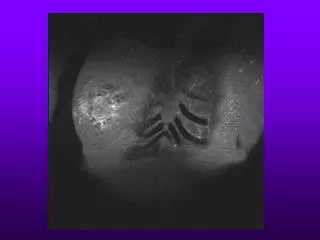
Introduction • Breast cancer screening programs depend on x-ray mammography because it is a low-cost, low-radiation-dose procedure that has the sensitivity for early detection and improved treatment. • Recognition of breast cancer depends on • the detection of masses, particularly with irregular or “spiculated” (Strands of tissue radiating out from an ill-defined mass, producing a stellate appearance) margins • clusters of microcalcifications (specks of calcium hydroxyapatite) • architectural distortions of breast structures
Introduction • Mass with spiculated margins • Clustered heterogeneous microcalcifications • Architectural distortion c.f. Pictorial Essay : Mammographic Features of Breast Cancer, MB Popli, Ind J Radiol Imag 2001 11:4:175-179
Introduction • Mammography – Find Cancer • the AMA, ACS and ACR recommends a baseline mammogram by age 40, biannual examinations between ages 40 and 50, and yearly examinations after age 50 • NCI recommends women in their 40s, 50s and older should be screened every one to two years with mammography • requires craniocaudal (CC) and mediolateral oblique (MLO) views of each breast
Introduction • Diagnostic Mammography – Evaluate Abnormalities • may require additional views, magnification views, spot compression views, stereotactic biopsy or other studies using other modalities
Mammographic Imaging Modalities • Ultrasound Breast Imaging • used for differentiating cysts (typically benign) from solid masses (often cancerous), which have similar appearances on the mammogram • provides biopsy needle guidance for extracting breast tissue specimens • MRI • has wonderful tissue contrast sensitivity • useful for evaluating silicone implants • accurately assess the stage of breast cancer involvement
Modern Mammography • Breast is composed of fatty tissue, glandular tissue, and connective tissue. • Normal and cancerous tissues in the breast have small x-ray attenuation differences between them • Need x-ray equipment specifically designed to optimize breast cancer detection
Modern Mammography • Detection of minute calcifications important • high correlation of calcification patterns with disease • Best differential between the tissues is obtained at low x-ray energies • Mammography equipment • Low contrast sensitivity • high resolution • low dose
Modern Equipment • Dedicated Mammography Equipment • Specialized X-ray Tubes • Optimized Screen/Film detector systems • Breast Compression Devices
X-ray Tube Design • Cathode and Filament Circuit • Low operating voltage • below 35 – 40 kVp • Typically 23 or 24 kVp at the lowest • dual filaments in a focusing cup • 0.3 mm (contact) and 0.1 mm (magnification) focal spot sizes • small focal spot • minimizes geometric blurring • maintains spatial resolution • Typical tube currents are • 100 mA (+/- 25 mA) for large (0.3 mm) focal spot • 25 mA (+/- 10 mA) for small focal spot
X-ray Tube Design • Anode • rotating anode design • Molybdenum (Mo), and dual track molybdenum/rhodium (Mo/Rh) targets are used • Characteristic x-ray production is the major reason for choosing molybdenum and rhodium • For molybdenum, characteristic radiation occurs at 17.5 and 19.6 keV • For rhodium, 20.2 and 22.7 keV
X-ray Tube Design • Anode • Targets used in combination with specific tube filters to achieve optimal energy spectra • A source to image distance (SID) of 60 to 66 cm typically used • The tube is tilted by about 25 degrees to minimize the effective focal spot size
X-ray Tube Design • Heel effect - lower x-ray intensity on the anode side of the field (attenuation through the target) • Thus cathode-anode axis is placed from the chest wall (greater penetration of x-rays) to the nipple in breast imaging • A more uniform exposure is achieved • This orientation also minimizes equipment bulk near the patient’s head for easier positioning
Tube Port, Tube Filtration, and Beam Quality • Monoenergetic x-rays of 15 to 25 keV are best choice, but not available • Polychromatic spectra compromises: • High-energy x-rays in the bremsstrahlung spectrum diminish subject contrast • Low-energy x-rays in the bremsstralung spectrum have inadequate penetration and contribute to patient dose without providing a useful image • Molybdenum (Mo) and Rhodium (Rh) are used for mammography targets and produce characteristic x-ray peaks at 17.5 and 19.6 keV (Mo) and 20.2 and 22.7 keV (Rh)
Tube Port, Tube Filtration, and Beam Quality • 1-mm thick Beryllium used as the tube port • Beryllium provides both low attenuation and good structural integrity • Added tube filters of the same element as the target reduce the low- and high-energy x-rays in the x-ray spectrum and allow transmission of characteristic x-ray energies • Common target/filters in mammography include • Mo/Mo • Rh/Rh • Mo/Rh
Tube Port, Tube Filtration and Beam Quality • A Mo target with Rh filter are common for imaging thicker and denser breasts • This combination produces slightly higher effective energy than Mo/Mo • Provides 20 and 23 keV leading to increased penetration of thick and/or dense breasts
Tube Port, Tube Filtration and Beam Quality • Rh target with Rh filter provides the highest effective energy beam • 2 to 3 keV higher • useful for the thickest and densest breasts • Tungsten (W) targets with Rh filter is used only on certain manufacturer’s unit
Half Value Layer (HVL) • The HVL ranges from 0.3 to 0.45 mm Al in mammography • depends on kVp, compression paddle thickness, added tube filtration, target material and age of tube. • In general, HVL increases with higher kVp and higher atomic number targets and filters. • Breast dosimetry relies on accurate HVL measurement • The approximate HVL in breast tissue is ~ 1 to 2 cm (strongly dependent on tissue composition: glandular, adipose and fibrous). • Thus a 4cm breast will attenuate 1-1/24 0.93, or 93% of the incident primary radiation • [reduction in beam intensity or fraction transmitted is 1/2n and attenuation is (1-1/2n)]
Collimation • Fixed-size metal apertures or variable field size shutters collimate the x-ray beam. • The field size matches the film cassette sizes • 18 x 24 cm or 24 x 30 cm • The x-ray focal spot and the collimator defines the radiation field • The light bulb filament, the mirror, and the collimator define the x-ray field • X-ray field – light field congruence must be within 2% of SID for any edge • The useful x-ray field must extend to the chest wall edge without field cutoff
X-ray Generator • A dedicated mammography x-ray generator is similar to a standard x-ray generator in design and function. Differences exist in • Generator power rating is 3 kW • The voltage supplied to the x-ray tube (22-40 kVp), • Automatic Exposure Control (AEC) circuitry different • High-frequency generators are the standard for mammography
Automatic Exposure Control (AEC) • The AEC, also called a phototimer, uses a radiation sensor (or sensors), an amplifier, a voltage comparator, to control the exposure • AEC detector is located underneath the cassette in mammography unlike conventional radiography
Automatic Exposure Control (AEC) • If the transmission of photons is insufficient to trigger the comparator switch, then after an extended exposure time, a backup timer terminates the exposure. • For a retake, the operator must select a higher energy beam for greater beam penetrability, thus permitting a shorter exposure time. A higher energy is possible by selecting a higher kVp, a higher energy filter, a higher energy target, or combinations.
Technique Chart • Technique charts are useful guides to determine the appropriate kVp for specific imaging tasks, based on breast thickness and breast composition • posted near the console • Proper kVp is essential for a reasonable exposure time, defined as a range from approx. 0.5 to 2.0 seconds, to achieve an optical density of 1.5 to 2.0
Take Home Points • Breast Cancer – masses, microcalcifications and architectural distortions in breast • Low energies used to optimize contrast (photoelectric effect) • Specialized equipment needed • Improve contrast and resolution, decrease dose • kVp range 22- 40 kVp
Take Home Points • Molybdenum and Rhodium (sometimes W) targets used in mammography • Characteristic radiation for Mo at 17.5 and 19.6 keV • For Rh, 20.2 and 22.7 keV • Heel effect due to attenuation in target • Chest wall on cathode side and nipple on anode side to get uniform exposure.
Take Home Points • Breast Cancer – masses, microcalcifications and architectural distortions in breast • Low energies used to optimize contrast (photoelectric effect) • Specialized equipment needed • Improve contrast and resolution, decrease dose • kVp range 22- 40 kVp • Molybdenum and Rhodium targets used in mammography • Characteristic radiation for Mo at 17.5 and 19.6 keV • For rhodium, 20.2 and 22.7 keV • Heel effect due to attenuation in target • Chest wall on cathode side and nipple on anode side to get uniform exposure
Take Home Points • Common target/filters in mammography include • Mo/Mo (thin breasts), Mo/Rh (thicker, denser breasts), Rh/Rh (thickest, dense breasts), • Tungsten target available on some units but not used • Generator similar to conventional radiography except for • lower power rating, different AEC circuitry, low kVp used • 18 x 24 and 24 x 30 cm cassettes used • AEC detector is located underneath the cassette in mammography unlike conventional radiography
Compression • Breast compression is necessary • it reduces overlapping anatomy and decreases tissue thickness of the breast • less scatter, more contrast, less geometric blurring of the anatomic structures, less motion and lower radiation dose to the tissues
Compression • Compression is achieved with a low attenuating lexan paddle attached to a compression device • 10 to 20 Newtons (22 to 44 pounds) of force is typically used • A flat, 90°paddle (not curved) provides a uniform density image • Parallel to the breast support table • Spot compression uses small paddles • Principal drawback of compression is patient discomfort
Scatter Radiation • Scatter radiation degrades subject contrast • The amount of scatter increases with breast thickness and breast area, and is relatively constant with kVp (25-35 kVp) • Without scatter rejection, only 50 to 70% of the inherent subject contrast will be detected.
AntiScatter Grid • Grids are used to reject scatter. • The grid is placed between the breast and the image receptor. • Linear grids with a grid ratio of 4:1 to 5:1 are typical. Cellular grids used by one manufacturer. • Higher grid ratios provide greater x-ray scatter removal but also a greater dose penalty. • Organic fiber or carbon fiber are typical interspace materials. • Carbon fiber is preferred because aluminum would attenuate too many of the low-energy x-rays used in mammography
AntiScatter Grids • Grid frequencies (lead strip densities) range from 30 to 50 lines/cm for moving grids and up to 80 lines/cm for stationary grids • The Bucky factor is the ratio of exposure with the grid compared to the exposure without the grid for the same film optical density. • For mammography, Bucky factor is about 2 to 3, so breast dose is doubled or tripled, but image contrast improves by 40%.
Air Gaps • The use of an air gap between the patient and the screen-film detector reduces the amount of detected scatter • Grids not used in magnification, air gap used. • Reduction of the breast dose is offset by the shorter focal spot to skin distance. • Reduction of the breast dose is offset by the shorter focal spot to skin distance
Magnification • Advantages • Magnification of 1.5x to 2.0x is used • Increased effective resolution of the image receptor by the magnification factor • Small focal spot size used • Reduction of scatter
Magnification • Disadvantages • Geometric blurring caused by the finite focal spot size (more on cathode side) • High breast dose (in general similar to contact mammography) • Long exposure times (small focal spot, low mA) • patient motion and blur
MTF in magnification mammography c.f. Bushberg, et al. The Essential Physics of Medical Imaging, 2nd ed., p. 211.
Screen-Film Cassettes • Cassettes have a single phosphor screen and single emulsion film • Mammography screen-film speeds (sensitivity): • regular (100 speed) (12-15 mR required) • medium (150 – 190 speed) • For comparison, a conventional “100-speed” screen film cassette requires about 2 mR
c.f. Bushberg, et al. The Essential Physics of Medical Imaging, 2nd ed., p. 214. • Limiting spatial resolution is about • 15-20 lp/mm (0.025 - 0.030 mm object size)
Film Processing • Film processing is a critical step in the mammographic imaging chain • Consistency in film speed, contrast, optical density levels are readily achieved by following the manufacturer’s recommendations
Film Processing • A film processor quality control program is required by the Mammography Quality Standards Act of 1992 (MQSA) regulations, and daily sensitometric strips prior to the first clinical images must verify acceptable processor performance. • Film sensitometry confirms proper film contrast, speed and base + fog values of mammographic film • Typical fog values are 0.17 – 0.2 OD, Dmax = 3.8 – 4.0 OD and the target film OD ranges from 1.2 – 1.8.
Film Sensitometry c.f. Bushberg, et al. The Essential Physics of Medical Imaging, 2nd ed., p. 216.
c.f. Bushberg, et al. The Essential Physics of Medical Imaging, 2nd ed., p. 226.
Extended Cycle Processing • Not done very much anymore. • Extended cycle processing (or push processing) increases the speed of some single emulsion mammography films by extending the developer immersion time by a factor of two (usually from ~ 20 to ~ 40 seconds). • The rationale is to completely develop all latent image centers, which does not occur with standard processing. • Up to 35% to 40% decrease in required x-ray exposure is obtained compared to standard processing for same OD. • On conventional 90 second processor, the processing time is extended to 180 seconds.
Extended Cycle Processing c.f. Bushberg, et al. The Essential Physics of Medical Imaging, 2nd ed., p. 218.
Viewing Conditions • Optimal film viewing conditions are important in detecting subtle lesions. • Mammography films are exposed to high optical densities to achieve high contrast, view boxes providing a high luminance are necessary. • The luminance of a mammography viewbox should be at least 3000 cd/m2 (nit). • In comparison, a typical viewbox in diagnostic radiology is about 1500 cd/m2 (nit).
Viewing Conditions • Film masking is essential for blocking clear portions of the film and the viewbox. • The ambient light intensity in a mammography reading room should be low to eliminate reflections from the film. • A high intensity bright light to penetrate high optical density regions of the film, such as skin line and the nipple area. • Magnifiers should be available to view fine detail such as microcalcifications.
Radiation Dosimetry • Risk of carcinogenesis from the radiation dose to the breast is of concern thus monitoring of dose is important and is required yearly by MQSA (Mammography Quality Standards Act of 1992) • Indices used in Mammography • Entrance Skin Exposure (ESE) • the free-in-air ionization chamber measurement of the entrance skin exposure of the breast • typical ESE values for a 4.5 cm breast are 500 to 1000 mR • Half Value Layer (HVL) • Typical HVL from 0.3 to 0.4 mm Al for 25 – 30 kVp