Download
1 / 72
750 likes | 997 Views
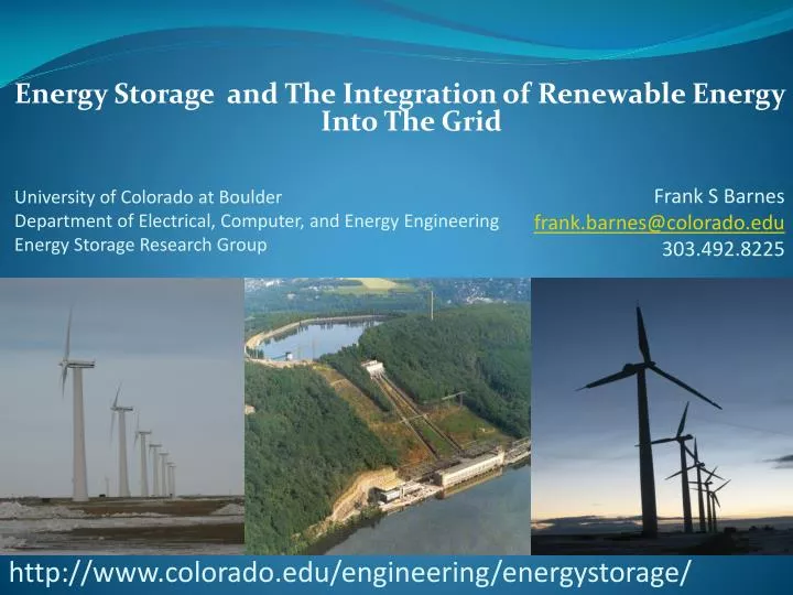
Energy Storage and The Integration of Renewable Energy Into The Grid. University of Colorado at Boulder Department of Electrical, Computer, and Energy Engineering Energy Storage Research Group. Frank S Barnes frank.barnes@colorado.edu 303.492.8225.

E N D
Energy Storage and The Integration of Renewable Energy Into The Grid University of Colorado at BoulderDepartment of Electrical, Computer, and Energy EngineeringEnergy Storage Research Group Frank S Barnes frank.barnes@colorado.edu 303.492.8225 http://www.colorado.edu/engineering/energystorage/
Acknowledgements The work leading to this talk was conducted by • Jonah Levine • Michelle Lim • MohitChhabra • Brad Lutz • Greg Martin • Muhammad Awan • TahaHarnesswala • Richard Moutoux • CameliaBouf • Kimberly Newman
Outline of Our Work 1. Potential Location of Pumped Hydroelectric Storage in Colorado 2. Issues in Compressed Air Storage at 1500m in Eastern Colorado 3. The use of battery storage for frequency control and voltage regulation 4. Feed In Angle for Solar Power 5. The Optimization of Energy Use in Water Systems. 6. Detection of Power Theft 7. Optimization of Energy Use in Water Systems
Obstacles to Integration of Wind and Solar Energy The Variability of Wind, Solar and Hydroelectric Power and Mismatch to the Loads The Integration and Control of a Large Number of Distributed Sources in to the Grid Lack of low cost convenient energy storage systems
Simplified System Model frequency Steam Generator + Gas Generator Network Electric System - + Wind Generators Sbase= 600MVA + Energy Storage System (ESS) + Load Reference: [2]-[4]
Input Data Sbase = 600 MVA 11th Jan 2011: 1 pm 9th June 2011: 1 pm
Frequency - Winter ~32% wind penetration
Frequency - Summer ~29% wind penetration
Power Spectrum [1] Turbine upper limit small magnitude:turbine acts aslow-pass filter Short-term Short-term Storage Time Scale : ≈ 10 sec – 3 hrs Energy Storage 278 hours 27.8 hours 2.78 hours 16.7 min 100 sec 10 sec 2 sec
References [1] J. Apt, “The spectrum of power from wind turbines”, Journal of Power Sources, v.169, March 2007 [2] G. Lalor, A. Mullane, M. O’Malley, "Frequency Control and Wind Turbine Technologies“, IEEE Transactions on Power Systems, v. 20, no.4, November 2005 [3] R. Doherty et al, “An Assessment of the Impact of Wind Generation on System Frequency Control", IEEE Transactions on Power Systems, v.25, no.11, February 2010 [4] P. Kundur, Power System Stability & Control, McGraw-Hill, 1994
Xcel PSCo Load Duration Curve and Net Load Duration Curves Min Coal Generation
Case When Wind Energy Exceeds Capacity. • Current Law Requires use of Wind Energy • The wind energy may exceed the amount of gas fired energy that can be shut off and require the reduction of heat rate to coal fired plants • This reduces electric power generation efficiency and increase emissions of SO2, NOx and CO2 for old plants • It is expected to up to double the costs of maintenance.
Emissions for Start Up, Ramping and Partial Loads • IEEE Power systems Nov-Dec. 2013
Cost of Increasing Wind Energy Penetration Gas Cost Impact of wind penetration with and without storage on Xcel’s electric grid Cost Impact of increasing wind penetration on Xcel’s electric grid
Lower Bound on Cycling Costs • IEEE Power Systems Nov-DEC 2013
Approaches to Solving the Variability Issues. • At low penetration grid spinning reserves. • Gas fired generators • Storage • Batteries, super capacitors, fly wheels • Pumped Hydroelectric systems, CAES • Demand Response • Biomass, geothermal
Comparison of efficiency of several energy storage technologies NREL report
Potential Locations and Capacity for Pumped Hydro in Colorado • 1
Pumped Hydro Storage in Colorado Wind Integration Study for Public Service of Colorado Addendum Detailed Analysis of 20% Wind Penetration http://www.xcelenergy.com/SiteCollectionDocuments/docs/CRPWindIntegrationStudy.pdf
Snapshot of Pumped Storage Globally Rick Miller HDR/DTA Pump Storage Units in Operation (MW) by Country/Continent Pumped Storage Projects Under Construction (MW)
Compressed Air Energy Storage CAES Questions of Interest • Where can we locate CAES.? • Some Design Considerations • Value of Storage • When is it Cost Effective?
Current and Planned CAES Systems 1.Huntorf Germany 1978 290 MW for 2 to 3 hours per cycle 2. McIntosh, Alabama 110 MW ,19 million cubic feet and 26 hours per charge 3. Others that have been under discussion for a long time A. Iowa Stored Energy Park B. Norton Ohio (2700 MW) 4. Others?
CAES Characteristics 1. It is a hybrid system with energy stored in compressed air and need heat from another source as well. 2. Require 0.7 to 0.8 kWh off peak electrical energy and 4100 to 4500 Btu (1.2 -1.3 kWh) of natural gas for 1 kWh of dispatchable electricity 3. This compares with ~ 11,000 Btu/kWh for conventional gas fired turbine generators. 4. Efficiency of electrical energy out to electrical plus natural gas energy in ~ 50%
CAES Characteristics • Another way to calculate efficiency is comparing to the normal low efficiency of natural gas turbines with heat rate of 11000 Btu/kWh yielding 0.39 kWh of electricity and adding 0.75 kWh off peak electricity to get 1.14 kWh’s to get 1 kWh of dispatchable electricity • This gives an efficiency of 88% • There are two types of CAES systems • Underground CAES • Above ground CAES
Underground CEAS • Potential for large scale energy storage – 100 to 300 MW for 10 – 20 hours. • Effective in performing load management, peak shaving, regulation and ramping duty. • Less capital cost compared to other large scale energy storage options. Main components of underground CAES
Challenges associated with Underground CAES • Identification of suitable site for setting up a underground facility. • Optimizing the compression process to reduce the compression work required. • Thermal management – efficiently extracting, storing and reusing the available heat of compression, thus improving the efficiency of the system. • Understanding the effect of cyclic loading and unloading on the structural integrity of the underground cavern.
Deep CAES • Deep compressed air energy storage is an underground CAES facility where the cavern is formed at depths of >4000 ft. as against 1000-2000 ft. in case of conventional facilities. • The main advantage of going deep are, • Maximum permissible operating pressure of a cavern increases with depth. - A good approximation will be 0. 75 to 1.13 psi/ft. based on the local geology. • Hence going deep helps store air at higher pressures in much smaller cavern volume, hence higher energy density. The possibility of setting up a deep compressed air energy storage facility in Eastern Colorado is being currently investigated by Energy Storage Research group at CU, Boulder.
Challenges associated with Deep CAES Deep CAES brings in additional challenges, which are • Utilizing the high pressure compressed air effectively. Most of the off-the-self gas turbines operate in the range of 70-100 bars, hence it is necessary to design the system such that high pressures can be utilized. • Understanding the effect of high pressure & temperature on the cavern structure. • Identifying suitable equipment's / material to operate at high pressure . • Potential for leakage through faults.
Criteria for Site Selection 1. Tight Cavern 2. Adequate natural gas 3. Ability to withstand 600 to 1200psi for conventional & 2000 – 5000 psi for deep CAES. 4. Proximity to Wind or Load to minimize transmission line losses. 5. Appropriate geology 6. A report by Cohn et al. 1991 “Applications of air saturation to integrated coal gasification/CAES power plants. ASME 91-JPGC-GT-2 says that this can be found in 85% of the US.
Possible Geologies 1. Abandoned Natural Gas fields. 2. Old Mines 3. Dome Aquifers 4. Porous Sandstone 4. Salt Domes 5. Bedded Salt
Why Salt Beds / Domes? Salt beds are more desirable for setting up new Caverns because of the following reasons, • Easy to be solution mined • Salt has good Elasto-plastic properties resulting in minimal risk of air leakage • Salt deposits are widespread in many of the subsurface basins of the continental US, including western states (Colorado, West Texas, Utah, North Dakota, Kansas)