Download
1 / 14
230 likes | 1.09k Views
Mechanism to open and close a window. Kinematic diagram. Kinematic (stick or skeleton) Diagrams. A striped-down (simplified) drawing showing the essentials needed for kinematics analysis. All links are numbered while the joints are lettered. Kinematic (stick or skeleton) Diagrams.

E N D
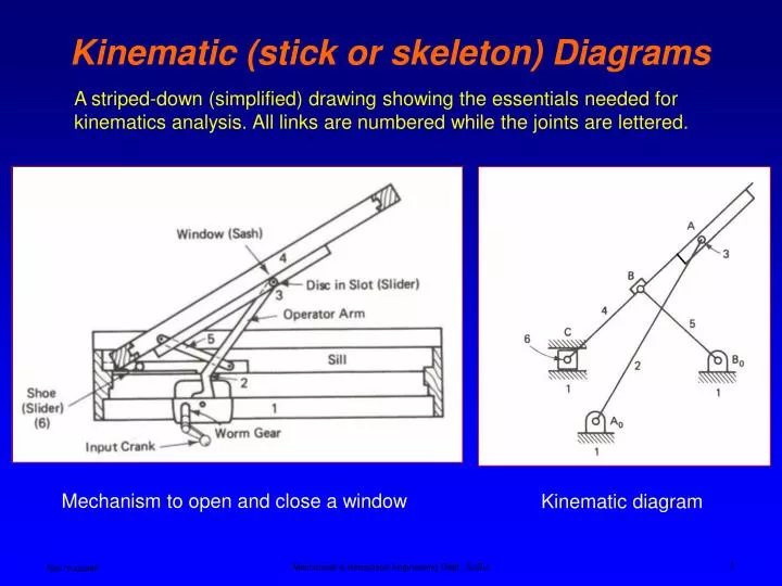
Mechanism to open and close a window Kinematic diagram Kinematic (stick or skeleton) Diagrams A striped-down (simplified) drawing showing the essentials needed for kinematics analysis. All links are numbered while the joints are lettered. Mechanical & Aerospace Engineering Dept., SJSU
Kinematic (stick or skeleton) Diagrams Mechanical & Aerospace Engineering Dept., SJSU
Indicating a rigid link Indicating a fixed angle plate Kinematic (stick or skeleton) Diagrams Hydraulic actuator Mechanical & Aerospace Engineering Dept., SJSU
Degrees of Freedom An object in space has six degrees of freedom. • Translation – movement along X, Y, and Z axis (three degrees of freedom) • Rotation – rotate about X, Y, and Z axis • (three degrees of freedom) Mechanical & Aerospace Engineering Dept., SJSU
Degrees of Freedom (DOF) Planar (2D) mechanisms Degrees of Freedom– number of independent coordinates required to completely specify the position of the link Three independent coordinates needed to specify the location of the link AB, xA, yA, and angle An unconstrained link in the plane has three degrees of freedom, mechanism with L links has 3L degrees of freedom Mechanical & Aerospace Engineering Dept., SJSU
Type of Joints – Kinematic Pairs Lower Pairs – motion is transmitted through an area contact, pin and slider joints. Higher Pairs– motion is transmitted through a line or a point contact; gears, rollers, and spherical joints. Mechanical & Aerospace Engineering Dept., SJSU
Each pin connection removes two degrees of freedom of relative motion between two successive links. Two degrees of freedom joints are sometimes called a half a joint (Norton). A slider is constrained against moving in the vertical direction as well as being constrained from rotating in the plane. A spheric pair is a ball and socket joint, 3 DOF. The helical pair has the sliding and rotational motion related by the helix angle of the screw. Planar pair is seldom used Degrees of Freedom (DOF) – Type of Joints, Lower Pairs Mechanical & Aerospace Engineering Dept., SJSU
Rolling contact (no sliding), 1 DOF Gears – sliding and rotation motion between two teeth, 2 DOF Degrees of Freedom (DOF) – Type of Joints, Higher Pairs Roll-slide contact, 2 DOF Mechanical & Aerospace Engineering Dept., SJSU
Spring – no effect on mechanism DOF Degrees of Freedom (DOF) – Type of Joints, Higher Pairs Belt and pulley (no sliding) or chain and sprocket – 1 DOF Mechanical & Aerospace Engineering Dept., SJSU
DOF ≤ 0 structure mechanism DOF > 0 Degrees of Freedom (DOF) Kutzbach’s (modified Groubler) equation DOF = 3(L – 1) – 2J1 – J2 DOF = degree of freedom or mobility L = number of links, including ground link J1 = number of 1 DOF joints (full joints) J2 = number of 2 DOF joints (half joints) Mechanical & Aerospace Engineering Dept., SJSU
DOF = 3(L – 1) – 2J1 – J2 DOF = 3(4 – 1) – 2(4) – (0) = 1 Slider crank mechanism L = 4 , J1 = 3 pin connections + 1 slider = 4 J2 = 0 DOF = 3(4 – 1) – 2(4) – (0) = 1 Degree of Freedom (DOF) – example Four Bar mechanism L = 4 , J1 = 4 pin connections, J2 = 0 1 DOF means only one input (power source) is needed to control the mechanism Mechanical & Aerospace Engineering Dept., SJSU
10 9 8 7 9 8 6 5 6 5 4 3 DOF = 3(L – 1) – 2J1 – J2 = 3(12-1) -2(15) = 3 3 2 1 2 Degrees of Freedom (DOF) – trench hoe Number of links, L = 12, Number of one DOF joints, J1 = 12 (pins) + 3 (slider) = 15, 11, 12 Number of two DOF joints, J2 = 0 11 12 10 7 4 3 hydraulics are used to control the position of the bucket. 1 Mechanical & Aerospace Engineering Dept., SJSU
1 DOF = 3(L – 1) – 2J1 – J2 = 3(7-1) – 2(7) – 1 = 3 1 1 Degree of Freedom (DOF) - example Number of links, L = 7, Number of one DOF joints, J1 = 6 (pins) + 1 (slider) = 7, Number of two DOF joints, J2 = 1 (fork joint) Three input sources are needed to control the mechanism Fork Joint 4 3 2 Spring 5 Slider 6 7 Mechanical & Aerospace Engineering Dept., SJSU
L = 3, J1 = 3, J2 = 0 DOF = 3(3-1) - 2(3) = 0 Redundant support 3 L = 5, J1 = 6, J2 = 0 4 DOF = 3(5-1) - 2(6) = 0 2 5 Paradoxes Two rollers in contact, no slipping Mechanical & Aerospace Engineering Dept., SJSU