Download
1 / 17
170 likes | 338 Views
Engineering 1040: Mechanisms & Electric Circuits Fall 2011. Interfacing Light-Emitting Diodes (LEDs) & Push Buttons to Microcontrollers. Light-Emitting Diodes (1). Source: Wikipedia (http://en.wikipedia.org/wiki/Light-emitting_diode). Light-Emitting Diodes (2). An LED is a diode

E N D
Engineering 1040: Mechanisms & Electric Circuits Fall 2011 Interfacing Light-Emitting Diodes (LEDs) & Push Buttons to Microcontrollers
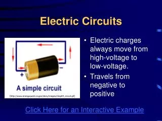
Light-Emitting Diodes (1) Source: Wikipedia (http://en.wikipedia.org/wiki/Light-emitting_diode)
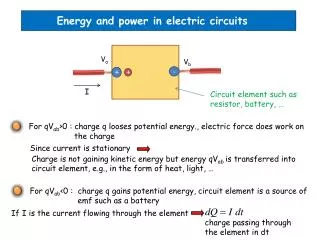
Light-Emitting Diodes (2) • An LED is a diode • Its emitter comprises of a semiconductor die. It has a cathode and an anode. • Usually a diode allows an electric current to pass only in one direction. • When an LED is connected to a circuit its forward current should not exceed a maximum allowable limit. • We can limit this current by using current limiting resistors.
Methods of interfacing LEDs to a microcontroller Method 1 Method 2 What is the value of R?
Interfacing push buttons to the microcontroller • Switches are used to make, break or change connections in an electrical circuit. • Push button switches are usually spring loaded so it returns the moving element to the original position when the pushing force is removed. • There two types of push buttons. Normally Open Switch Normally Closed Switch
Interfacing Push Buttons “Normally Open“ Push Button “Normally Closed" Push Button
LED 3 Pin D0 LED 2 Pin D1 Reset Pin 1 (MCLR) Bootload Pin 33 (B5)
Set pin D0 as Output Port (LED) Set Pin B5 as Input Port (switch) Set all pins of PORT D0 as zero Set sw equals to 0010000 in binary
PORTB & 0x20 = PORTB AND 0b00100000 When the button is released pin B5 is set to HIGH, PORTB=0b00100000 or 0x20 When the button is pressed pin B5 is set to LOW, PORTB=0b00000000 or 0x00
Before the button is pressed pin B5 is HIGH • PORTB=0b00100000 or 0x20 • Then sw becomes, sw=0x20 & 0x20 = 0x20; • Since sw= 0x20, the condition is TRUE so the code will remain in the while loop . • When the button is pressed pin B0 is LOW. • PORTB=0 or PORTB=0x0 • Then sw becomes, sw=0x00 & 0x20 = 0; • Since sw=0, the condition is FALSE so the code will exit the while loop . LED is OFF sw = 1 LED is ON sw = 0 • Sets the pin D1 to HIGH • When pin D1 is HIGH it lights the LED • Sets a delay for button debounce LED is ON
Now the button is pressed • So pin B5 is LOW • PORTB=0b00000000 or 0x00 • Then sw becomes, sw=0x00 & 0x20 = 0; • Since sw= 0, the condition is TRUE so the code will remain in the while loop . • When the button is released pin B0 is HIGH. • PORTB=0b00100000 or PORTB=0x20 • Then sw becomes, sw=0x20 & 0x20 = 0x20; • Since sw= 0x20, the condition is FALSE so the code will exit the while loop . LED is ON sw = 0 sw = 1 • Sets a delay for button debounce LED is ON
NOW the button is released pin B5 is HIGH • PORTB=0b00100000 or 0x20 • Then sw becomes, sw=0x20 & 0x20 = 0x20; • Since sw= 0x20, the condition is TRUE so the code will remain in the while loop . • When the button is pressed pin B0 is LOW. • PORTB=0 or PORTB=0x0 • Then sw becomes, sw=0x00 & 0x20 = 0; • Since sw=0, the condition is FALSE so the code will exit the while loop . LED is ON sw = 1 LED is OFF sw = 0 • Sets the pin D1 to LOW • When pin D1 is LOW the LED stops to light • Sets a delay for button debounce
LED is OFF • Now the button is pressed • So pin B5 is LOW • PORTB=0b00000000 or 0x00 • Then sw becomes, sw=0x00 & 0x20 = 0; • Since sw= 0, the condition is TRUE so the code will remain in the while loop . • When the button is released pin B0 is HIGH. • PORTB=0b00100000 or PORTB=0x20 • Then sw becomes, sw=0x20 & 0x20 = 0x20 ; • Since sw= 0x20, the condition is FALSE so the code will exit the while loop . sw = 0 sw = 1 LED is OFF • Sets a delay for button debounce