Download

1 / 39
410 likes | 667 Views
LRFD - Steel Design. Dr. Ali I. Tayeh First Semester. Steel Design Dr. Ali I. Tayeh. Chapter 5-A. Beams. Beams : Structural members that support transverse loads and are therefore subjected primarily to flexure, or bending.

E N D
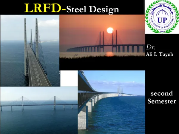
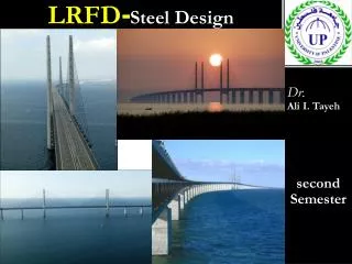
LRFD-Steel Design Dr. Ali I. Tayeh First Semester
Steel DesignDr.Ali I. Tayeh Chapter 5-A
Beams Beams: Structural members that support transverse loads and are therefore subjected primarily to flexure, or bending. structural member is considered to be a beam if it is loaded so as to cause bending Commonly used cross-sectional shapes include the W-, S-, and M-shapes. Channel shapes are sometimes used. Doubly symmetric shapes such as the standardrolled W-, M-, and S-shapesare the most efficient. AISC Specification distinguishes beams from plate girders on the basis of the width-thickness ratio of the web.
Beams Both a hot-rolled shape and a built up shape along with the dimensions to be used for the width-thickness ratios. If then the member is to be treated as a beam, regardless of whether it is a rolled shape or isbuilt-up.
If then the member is considered to be a plate girder.
Beams For beams, the basic relationship between load effects and strength is
Beams • BENDING STRESS AND THE PLASTIC MOMENT: • Consider the beam which is oriented so that bending is about the major principal axis • The stress at any point can be found from the flexure formula: • where M is the bending moment at the cross section underconsideration, y is the perpendiculardistance • For maximum stress, Equation takes the form: Where c is the perpendicular distance from the neutral axis to theextreme fiber, andSx is the elastic section modulus of the cross section.
Beams • BENDING STRESS AND THE PLASTIC MOMENT: • Equations are valid as long as the loads are small enough that the material remains within its linear elastic range. For structural steel, this means that the stress fmax must not exceed Fy and that the bending moment must not exceed • where My is the bending moment that brings the beam to the point of yielding.
Beams • BENDING STRESS AND THE PLASTIC MOMENT: • The plastic moment capacity, which is the moment required to form the plastic hinge, can easily be computed from a consideration of the corresponding stress distribution, From equilibrium of forces:
Beams • BENDING STRESS AND THE PLASTIC MOMENT: • The plastic moment, Mp is the resisting couple formed by the two equal and opposite forces, or
Beams • BENDING STRESS AND THE PLASTIC MOMENT: • Example 5.1: For the built-up shape, determine (a) the elastic section modulus S and the yield moment My and (b) the plastic section modulus Z and the plastic moment Mp-Bending is about the x-axis, and the steel is A572 Grade 50.
Beams Solution Because of symmetry, the elastic neutral axis (the x-axis) is located at mid-depth of the cross section (the location of the centroid ). The moment of inertia of the cross section can be found by using the parallel axis theorem, and the results of the calculations are summarized in the next table.
Beams • Example 5.1: Answer (A)
Beams • Because this shape is symmetrical about the x-axis, this axis divides the cross section into equal areas and is therefore the plastic neutral axis. The centroid of the top half-area can be found by the principle of moments. Taking moments about the x-axis (the neutral axis of the entire cross section) and tabulating the computations in the next Table, we get
answer Beams
Beams • Example 5.2 : • Solution
Beams • Example 5.2 :
Beams • STABILITY: • If a beam can be counted on to remain stable up to the fully plastic condition, the nominal moment strength can be taken as the plastic moment capacity ; that is Mn=Mp • When a beam bend.., the compression region (above the neutral axis) is analogous to a column, and in a manner similar to a column, it will buckle if the member is slender enough. Unlike a column however, the compression portion of the cross section is restrained by the tension portion, and the outward deflection (flexural buckling) is accompanied by twisting (torsion). • This form of instability is called lateral-torsional buckling (LTB). Lateral torsional buckling can be prevented by bracing the beam against twisting at sufficiently dose intervals
Beams • STABILITY: • This can be accomplished with either of two types of stability bracing: • Lateral bracing: which prevents lateral translation. should be app1ied as close to the compression f1ange as possible. • Torsional bracing :prevents twist directly. • The moment strength depends in part on the unbraced length, which is the distance between points of bracing.
Beams • CLASSIFICATION OF SHAPES:
Beams • BENDING STRENGTH OF COMPACT SHAPES:
Beams • BENDING STRENGTH OF COMPACT SHAPES: • We begin with compact shapes If the beam is compact and has continuous lateral support, or if the unbraced length is very short , the nominal moment strength, Mn is the full plastic moment capacity of the shape, Mp. • The first category, laterally supported compact beams, the nominal strength as
Beams • BENDING STRENGTH OF COMPACT SHAPES:
Beams • BENDING STRENGTH OF COMPACT SHAPES: • Example 5.3:
Beams • BENDING STRENGTH OF COMPACT SHAPES:
Beams • BENDING STRENGTH OF COMPACT SHAPES:
Beams • BENDING STRENGTH OF COMPACT SHAPES:
Beams • BENDING STRENGTH OF COMPACT SHAPES: Example 5.4
Beams • BENDING STRENGTH OF COMPACT SHAPES: Example 5.4 Cont.
Beams • BENDING STRENGTH OF COMPACT SHAPES:
Beams • BENDING STRENGTH OF COMPACT SHAPES:
Beams • BENDING STRENGTH OF COMPACT SHAPES: Example 5.5:
Beams • BENDING STRENGTH OF COMPACT SHAPES: Example 5.5 cont:
Beams • BENDING STRENGTH OF COMPACT SHAPES: Example 5.5 cont:
Beams • BENDING STRENGTH OF COMPACT SHAPES: Example 5.5 cont: