Download
1 / 17
170 likes | 279 Views
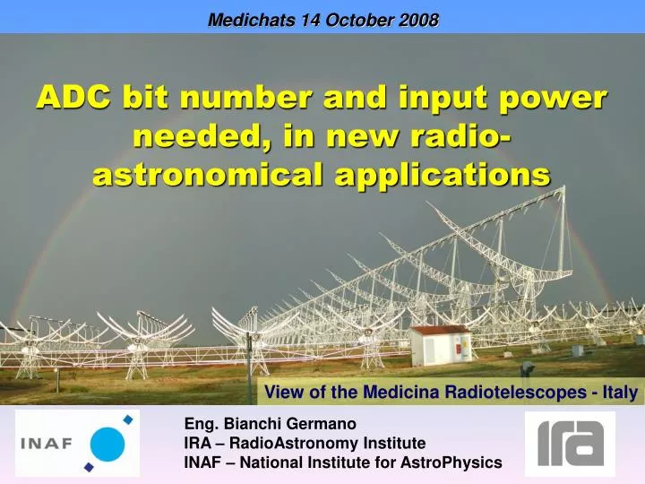
Medichats 14 October 2008. ADC bit number and input power needed, in new radio-astronomical applications. View of the Medicina Radiotelescopes - Italy. Eng. Bianchi Germano IRA – RadioAstronomy Institute INAF – National Institute for AstroPhysics. 5 Km. 700 mt.

E N D
Medichats 14 October 2008 ADC bit number and input power needed, in new radio-astronomical applications View of the Medicina Radiotelescopes - Italy Eng. Bianchi Germano IRA – RadioAstronomy Institute INAF – National Institute for AstroPhysics
5 Km 700 mt THE SKA PROJECT(Square Kilometer Array)
THE SKA PROJECT: features High sensitivity High resolution • Total area = 1Km2 (sensitivity > 100 time the VLA) • Large FOV (Field Of View) • Multiuser and Multitasking • Frequency coverage = 0.1-25 GHz • 4 GHz instantaneous band • Total cost = 1.5 billion €
RF spectrum scenario SKA band We have studied a procedure to estimate the required number of bit (resolution and dynamic) and the ADC input power level in radio astronomical applications.
BEST-2 BEST-1 BEST PROJECT (Basic Elements for SKA Training) The experiences gained with the BEST demonstrator is very suitable for the SKA community: in the final configuration it will have about 8000 m2 of collective area, a value comparable with the area of a proposed SKA station (about 10000 m2). • A-BEST-1: One single N/S antenna • - Ag=176 m2 Aeff=125 m2 • - Band: 16MHz @ 408MHz • -4 RX installed • B-BEST-2: 8 N/S antennas • - Ag=1410 m2 Aeff=1000 m2 • - Band: 16MHz @ 408MHz • -32 RX installed • C-BEST-3: 14 N/S antennas + 6 focal lines on the E/W arm. • - Ag=7300 m2 Aeff=5100 m2 • - Band: 16MHz @ 408MHz • -80 Rx installed
Radio relay stations Radio relay stations 16 MHz Scientific stratospheric balloon 4 MHz astronomical protected band RF spectrum scenario at the Medicina site
Which ADC is more suitable? BEST PROJECT ARCHITECTURE Front end (16 MHz @ 408 MHz + Optical Tx) Optical RX DIGITAL BACK-END A A D Fiber Optic Cable LO Receiver room
22 mt RFI Measurement campaign
Dynamic range estimation 0dBi the power level referred to an isotropic antenna (unitary gain in all directions). The equivalent system input noise power for 16 MHz bandwidth, in a single N-S antenna, is: The maximum dynamic range result:
Number of bit Pd = 37.8 dB How many bit correspond? Since an ADC converts voltage into bit and not power into bit, we need a relationship between the power and the voltage at the input of the A/D converter. If we consider the simplest possible situation, where there is only a monochromatic tone at the input of the ADC, we can easily find the relationship: VP = voltage peak (Volt) P = input power (dBm) From this equation, each bit corresponds to an increment of 3dB in voltage and 6dB in power.If we divide the dynamic range Pd by 6, we can obtain the required ADC number of bits. 7 bit The more the RF scenario is dominated by a strong signal, the more accurate the previous relationship is.
7 bit for RFIs 3 bit for the astronomical signal 10 bit -69.4 dBm Strongest RFIs level 37.8 dB (7 bit) -107.2 dBm Input noise level (KTsysB) • 107.2 dBm ? ? WHICH GAIN? P 3 bit AD6645 14 bit (ENOB = 12 bit @ 100MSPS) ADC 50
P G = 54.2 dB 3 bit - 53 dBm • 107.2 dBm G = 54.2 dB P -69.4 dBm Strongest RFIs level -53 dBm Input ADC level -69.4 dBm Strongest RFIs level -107.2 dBm Input noise level (KTsysB) ADC AD6645 50 ENOB = 12 bit VIN-PP = 2.2 V
POWER METER SPECTRUM ANALYSER ANTENNA RECEIVERS POWER SUPPLY LABVIEW PROGRAM LOGIC ANALYSER AND ADC CONFIGURATION PROGRAM ADC 14 bit, 100 MSPS Measurement bank
Results scientific stratospheric balloon radio relay stations
Results This measurement phase ran for few weeks to achieve data with the antenna pointed in all the directions. From the measures we performed, only 3 bit seem to be necessary to sustain the man made radio signals, so the ADC total bit required is 6: 3 bit for RFIs 3 bit for the astronomical signal 6 bits Following these considerations, an 8 bit A/D converter could work properly.
Infiniband CX4 Cables 5x Xilinx Virtex-2 Pro 70 Dual 1GS/sec @ 8 bit RX1 Ibob (Serializer) RX2 FPGA 1 FPGA 2 A/D1 AD2 Dual 1GS/sec @ 8 bit FPGA-5 RX n-1 Ibob (Serializer) A/D1 RXn FPGA-3 FPGA-4 AD2 4 x A/D @ 8 bit (1.0 GS/sec) Bee 2 BEST Back End ibob
Conclusion Estimated number of bit = 10 Number of bit measured = 6 • We attribute the difference between the estimated bit number and the measured one to the different antenna systems: • Yagi antennas pointed towards the horizon and working in the max-hold mode. • VERSUS • A half wavelength dipole focal line inside a cylindrical reflector pointed towards the sky. • We have concluded that our estimation method to valuate the number of bits is conservative, but applicable to radio astronomical scenario. • Further investigations should be performed to reduce the difference between the estimated and actual requested number of bit.