Download
1 / 22
220 likes | 300 Views
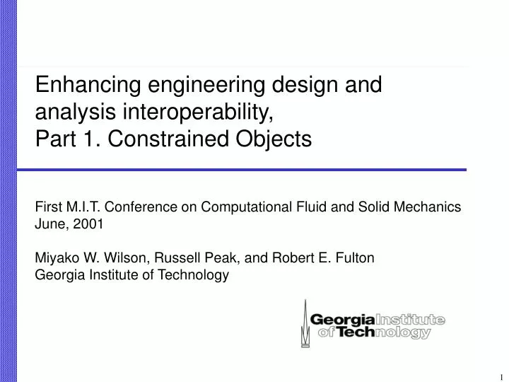
Enhancing engineering design and analysis interoperability, Part 1. Constrained Objects. First M.I.T. Conference on Computational Fluid and Solid Mechanics June, 2001 Miyako W. Wilson, Russell Peak, and Robert E. Fulton Georgia Institute of Technology. Motivation.

E N D
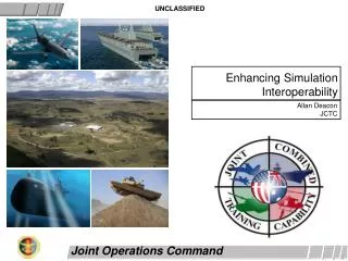
Enhancing engineering design and analysis interoperability, Part 1. Constrained Objects First M.I.T. Conference on Computational Fluid and Solid Mechanics June, 2001 Miyako W. Wilson, Russell Peak, and Robert E. Fulton Georgia Institute of Technology
Motivation • The need for a unified physical behavior modeling representation with the following characteristics • Has tailoring for design-analysis integration including supports for multi-fidelity idealization, product-specific analysis templates, and CAD-CAE tool interoperability. • Supports product information-driven analysis (I.e., supports plugging in detail design objects and idealizing them into a diversity of analysis models). • Has computer-processible lexical forms along with human-friendly graphical forms. • Represents relations in a non-casual matter (I.e., enables multi-directional combinations of model inputs/outputs). • Capture engineering knowledge in a modular reusable form
Constrained Object (COB) Overview - Techniques Leveraged • Object-oriented modeling [Lalonde & Pugh, et al.1990, Muller 1997] • class vs instance • inheritance • Constraint graph techniques [Borning, et al. 1990] • relations without fixed input/output direction • Declarative knowledge representation (non-casual) • Characterized by entities, attributes, and relations
COB RepresentationComponents Definition Languages Definition Languages Graphical Representations Graphical Representations Users Meta Information Model Meta Information Model Protocol Protocol Developers COB
Example COB Structure (COS)Spring Primitive Traditional Form Constraint Schematic-S Figure Relations COS Language COBspring ; undeformed_length, L<sub>0</sub> : REAL; spring_constant, k : REAL; start, x<sub>1</sub> : REAL; end, x<sub>2</sub> : REAL; length, L : REAL; total_elongation, ΔL : REAL; force, F : REAL; RELATIONS r1 : "<length> == <end> - <start>"; r2 : "<total_elongation> == <length> - <undeformed_length>"; r3 : "<force> == <spring_constant> * <total_elongation>"; END_COB; Subsystem View (for reuse by other COBs) Spring k F D L L 0 x L 1 x 2
Example COB Instance (COI)Spring Primitive Lexical COB Instance (COI) Constraint Schematic-I example 1, state 1.1 state 1.0 (unsolved): INSTANCE_OF spring; undeformed_length : 20.0; spring_constant : 5.0; total_elongation : ?; force : 10.0; END_INSTANCE; state 1.1 (solved): INSTANCE_OF spring; undeformed_length : 20.0; spring_constant : 5.0; start : ?; end : ?; length : 22.0; total_elongation : 2.0; force : 10.0; END_INSTANCE; Basic Constraint Schematic-I Notation
Multi-Directional I/O (non-causal)Spring Primitive Constraint Schematic-I Lexical COB Instance (COI) Design Verification example 1, state 1.1 state 5.0 (unsolved): INSTANCE_OF spring; undeformed_length : 20.0; spring_constant : ?; start : 10.0; length : 22.0; force : 40.0; END_INSTANCE; state 5.1 (solved): INSTANCE_OF spring; undeformed_length : 20.0; spring_constant : 20.0; start : 10.0; end : 32.0; length : 22.0; total_elongation : 2.0; force : 40.0; END_INSTANCE; Design Synthesis example 1, state 5.1
COB Representation Traditional Form: Spring System System Figure Free Body Diagrams System-Level Relations (Boundary Conditions) Variables and Relations Spring 1 Spring 2
COB Representation Constraint Graph: Spring System bc3 bc1 P bc4 F1 F2 k1 k2 r13 spring2 r23 spring1 x11 L1 L2 x22 r11 L1 L2 r21 r12 r22 x12 x21 bc6 L10 L20 bc5 u1 u2 bc2 Spring 1 Spring 2 System level Constraint Graph-S
COB Representation Extended Constraint Graph-S: Two Spring System Constraint Graph-S Extended Constraint Graph-S • Groups objects & relations into parent objects • Object-oriented vs. flattened partial (BC relations not included)
COB Representation Constraint Schematic: Spring System Elementary Spring k F D u L L 1 0 x L = x 0 1 11 x 2 Elementary Spring k F D L L u = D + u L u 0 2 2 2 1 x L 1 x 2 Constraint Graph-S P bc3 Constraint Schematic-S bc4 bc1 F 1 F k k 2 1 2 r13 spring2 r23 spring 1 spring1 x L L 11 1 x 2 22 D D L L r11 1 2 r21 r12 r22 x x 12 21 L L bc6 bc5 10 20 bc5 bc1 u u 1 2 bc2 bc2 bc3 spring 2 bc4 P • Encapsulated form (hides details) • Template re-usage bc6
COB Representation Constraint Schematic-S: Spring System Elementary Spring k F D u L L 1 0 x L = x 0 1 11 x 2 Elementary Spring k F D L L u = D + u L u 0 2 2 2 1 x L 1 x 2 Analysis Primitives with Encapsulated Relations spring 1 System-Level Relations (Boundary Conditions) bc5 bc1 bc2 bc3 spring 2 bc4 P bc6
COB Representation COS Language: Spring System COS Language Constraint Schematic-S COB spring_system ; spring1 : spring; spring2 : spring; deformation1, u<sub>1</sub> : REAL; deformation2, u<sub>2</sub> : REAL; load, P : REAL; RELATIONS r1 : "<spring1.start> == 0.0"; r2 : "<spring1.end> == <spring2.start>"; r3 : "<spring1.force> == <spring2.force>"; r4 : "<spring2.force> == <load>"; r5 : "<deformation1> == <spring1.total_elongation>"; r6 : "<deformation2> == <spring2.total_elongation> + <deformation1>"; END_COB;
COB Representation COB Instance (COI): Spring System COI Language Constraint Schematic-I state 1.0 (unsolved): INSTANCE_OF spring_system; spring1.undeformed_length : 8.0; spring1.spring_constant : 5.5; spring2.undeformed_length : 8.0; spring2.spring_constant : 6.0; load : 10.0; deformation2 : ?; END_INSTANCE; state 1.1 (solved): INSTANCE_OF spring_system; spring1.undeformed_length : 8.0; spring1.spring_constant : 5.5; spring1.start : 0.0; spring1.end : 9.818; spring1.force : 10.0; spring1.total_elongation : 1.818; spring1.length : 9.818; spring2.undeformed_length : 8.0; spring2.spring_constant : 6.0; spring2.start : 9.818; spring2.force : 10.0; spring2.total_elongation : 1.667; spring2.length : 9.667; spring2.end : 19.48; load : 10.0; deformation1 : 1.818; deformation2 : 3.485; END_INSTANCE;
COB Representation Lexical and Graphical Views Constraint Schematic-I COB Instance(COI) Language 100 lbs 20.2 in R101 30e6 psi 200 lbs Extended Constraint Graphs-I R101 20.2 in STEP 100 lbs Part 21 200 lbs 30e6 psi COB Structure (COS) COB Instance (COI) Constraint Schematic-S Subsystem -S view COB Structure (COS) Language I/O Tables Object Relationship Diagram Constraint Graphs-S Extended Constraint Graphs-S HTML Express-G STEP Express HTML Constraint Graph = Constraint Network
COB RepresentationComponents (see Wilson,2000) Definition Languages Definition Languages Graphical Representations Graphical Representations Users Meta Information Model Meta Information Model Protocol Protocol Developers COB
COB Meta Information Model & ProtocolGenericNature 22.0 20.0 2.0 10.0 32.0 5.0 L D L L F F x x 1 2 k 10.0 Generic Metadata Meta Information Model Protocol COB Structure Definition Data COB Instance Definition Data Generic Data COS COI Specific Structure Data Specific Instance Data Definition Languages Example: Graphical Representations
XaiTools ™X-Analysis Integration Toolkit COB Instances COB Structures Constraint Solver Mathematica FEA ANSYS Constraint Network Generic Viewer Java COB Definition Files Solvers API COB based Design/Analysis Tools
Using Internet/Intranet-based Analysis Solvers Thick Client Architecture Users Engineering Service Bureau Client PCs Host Machines Thick Client CORBA Daemon Iona orbixdj XaiTools CORBA IIOP CORBA Servers Internet XaiTools Ansys Solver Server XaiTools Ansys Solver Server XaiTools Math. Solver Server XaiTools Ansys Solver Server FEA Solvers Ansys Internet/Intranet ... Math Solvers Mathematica
XaiTools ™ COB BrowserSpring System • Functionality: • View • Change value • Change I/O • Activate/Disactivate relations
Constrained Object (COB) Representation • Capabilities & features: • Various forms: computable lexical forms, graphical forms • Sub/supertypes, basic aggregates, multi-fidelity objects • Multi-directionality (I/O change) • Wrapping external programs as white box relations • Analysis module/template applications (XAI): • Product model idealizations • Explicit associativity relations with design models & other analyses • White box reuse of existing tools (e.g., FEA, in-house codes) • Reusable, adaptable analysis building blocks • Synthesis (sizing) and verification (analysis)
Constrained Objects (cont.) Representation Characteristics & Advantages • Overall characteristics • Declarative knowledge representation (non-causal) • Combining object & constraint graph techniques • COBs = (STEP EXPRESS subset) + (constraint graph concepts & views) • Advantages over traditional analysis representations • Greater solution control • Richer semantics (e.g., equations wrapped in engineering context) • Unified view of diverse capabilities • Capture of reusable knowledge • Enhanced development of complex analysis models