Download
1 / 50
500 likes | 754 Views
The Illinois Society of Electroneurodiagnostic Technologists (ISET) Fall Meeting: Electronics Crash Course for Technologists. Saturday, November 9, 2013 Michael A. Stein, MD. Digital EEG System: Transformation. PART 2: ‘BlackBox’ Transformation. Digital EEG System: Transformation.

E N D
The Illinois Society of Electroneurodiagnostic Technologists (ISET)Fall Meeting:Electronics Crash Course for Technologists Saturday, November 9, 2013 Michael A. Stein, MD
Digital EEG System:Transformation • PART 2: • ‘BlackBox’ Transformation
Digital EEG System:Transformation • The next stage in the EEG system serves the following functions: • (1) Filtering of unwanted activity outside of the desired bandwidth. • (2) Amplification of Desired Signal within the bandwidth. • (3) Noise reduction.
Digital EEG System:Transformation • In this regards, 3 important characteristics of EEG amplifiers are: • (a) A flat frequency response within the passband (discussed in Part 1 of this course). • (b) A high common mode rejection ratio. • (c) A high input impedance. • The latter 2 properties will be discussed later in this course.
Digital EEG System:Transformation • First, a reminder from Part 1 about : • In this regards, 3 important characteristics of EEG amplifiers are: • (a) A flat frequency response within the passband (discussed in Part 1 of this course). • (b) A high common mode rejection ratio. • (c) A high input impedance.
In the case of a hi-fidelity sound system a bandwidth of approximately (20 – 20k Hz) with approximately equal gain is important since this is the range of audible frequencies. • If the gain is not approximately equal in this range then the reproduced sound heard by the listener will differ from the sound which was recorded.
Since the audio of cellular phones typically only includes voice data, the frequency response needs to have relatively equal gain over a narrower bandwidth of about (300 – 3,000)Hz.
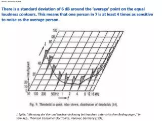
Since the EEG activity generated by the cortex which reaches the scalp has an even narrower bandwidth, and part of this is obscured by muscle artifact, the frequency response only needs to be equal in gain from about (0.5 - 70) Hz. • Since lower and higher frequencies consist of artifacts, they are deliberately filtered out.
Digital EEG System:Transformation • Although it is easier to understand these 3 functions if thought of separately, they are typically built into a single amplifier circuit. • (1) Filtering of unwanted activity outside of the desired bandwidth. • (2) Amplification of Desired Signal within the bandwidth. • (3) Noise reduction. Operational Amplifier – aka: OpAmp Differential Amplifier
Digital EEG System:Transformation:(1) Filtering of Unwanted Signal • Therefore, need to filter out frequencies that are both lower than and higher than the desired bandwidth of the signal being measured (EEG). • This can be done with either analog or digital electronics by use of both: • (1) Low frequency/high pass filters, and • (2) High frequency/low pass filters. • These two together (low frequency filter + high frequency filter) form a bandpass or passband filter. Ideally, the bandpass will be the same as the bandwidth of the desired signal (EEG). • In Part 1 the filtering which was discussed is due to the biophysical properties of the electrode and is unintended and can lead to degradation in EEG signal quality. • In contrast, at this stage of the EEG amplifier, the filtering is designed to filter out unwanted signals outside of the desired bandwidth, while passing EEG activity within the desired passband without change. Reminder from Part1:Terminology
Digital EEG System:Transformation:(1) Filtering of Unwanted Signal • Since there are both low frequency and high frequency sources of noise, both low frequency and high frequency filters are needed. • Examples of low frequency noise sources: • Cardiac pulsation • Sweat • Roving eye movements • Examples of high frequency noise sources: • Line/Mains/60 Hz • Medical devices (oscillating ventilators, etc.) • Cellular telephones, radios, etc. • Together these 2 filter types combine to form a bandpass filter. • The objectives of the bandpass filter are: • To filter out as much undesired signal as possible • To pass as much desired signal as possible without altering it
Digital EEG System:Transformation:(1) Filtering of Unwanted Signal (1) Low Frequency Filtering: • Since scalp EEG contains very low frequency information (slow wave sleep, slow spike and wave, etc.), the low frequency filter will need to have a low cutoff frequency. • In almost all systems there is overlap in frequency between desired signal and unwanted signal. • (e.g. Slow spike and wave and cardiac pulsation artifact). • A tradeoff is therefore necessary in the degree of filtering and the chosen cutoff frequency.
Reminder from Part 1:Digital EEG System:Low Frequency Filters • (A) Low frequency (aka high pass) filters: • (fc) = 1 / (2π x RC) = 1 / (2π x tc) • Example: • R = 10,000Ω • C = 16μF • (fc) = 1 / (2π x RC) = 1 / (2π x 10,000 x 16x10-6) = 1Hz. (Therefore, this circuit creates a single pole, low frequency filter with a cutoff frequency of 1 Hz.)
Digital EEG System:Transformation:(1) Filtering of Unwanted Signal (2) High Frequency Filtering: • Since scalp EEG begins to be obscured by muscle artifact above 30 Hz but EEG signal includes activity in this range as well, the high frequency filter cutoff frequency is chosen as a tradeoff between these factors. • In almost all systems there is overlap in frequency between desired signal and unwanted signal. • (e.g. Paroxysmal fast EEG activity and cellular telephone artifact).
Reminder from Part 1:Digital EEG System:High Frequency Filters • (A) High frequency (aka low pass) filters: • (fc) = 1 / (2π x RC) = 1 / (2π x tc) • Example: • R = 100Ω • C = 16μF • (fc) = 1 / (2π x RC) = 1 / (2π x 100 x 16x10-6) = 100 Hz. (Therefore, this circuit creates a single pole, high frequency filter with a cutoff frequency of 100 Hz.)
Digital EEG System:Transformation:(1) Filtering of Unwanted Signal • Together these two filters (low frequency filter and high frequency filter) create a bandpass filter. • Although this passband has some overlap with both low and high frequency sources of noise/artifact, these occur mostly beyond the 3 dB cutoff frequencies and will therefore be reduced in amplitude at the output of the EEG amplifier. + =
EEG Filter Examples:(1) Background Activity No filters Filters: (LFF = 1 Hz, HFF = 50 Hz)
EEG Filter Examples:(2) Interical Epileptiform Activity No filters Filters: (LFF = 1 Hz, HFF = 50 Hz)
EEG Filter Examples:(3a) Ictal/Seizure Activity No filters Filters: (LFF = 1 Hz, HFF = 50 Hz)
EEG Filter Examples:(3b) Ictal/Seizure Activity No filters Filters: (LFF = 1 Hz, HFF = 50 Hz, Notch Filter = 60 Hz)
Digital EEG System:Transformation:(2) Amplification of Desired Signal • Terminology: • Operational Amplifiers (aka: OpAmps). • Simple electronic circuits which amplify the signal so that the output is larger than the input. • Examples: • (1) Cellular telephone transmission: • Signal needs to be amplified so there is enough power to carry over great distances. • (2) Hi-fidelity sound system: • Signal needs to be amplified so there is sufficient power to mechanically move the loudspeakers enough to create audible sound. • (3) EEG system: • Signal needs to be amplified so that it is large enough to be viewed on a computer monitor.
Digital EEG System:Transformation:(2) Amplification of Desired Signal • There are different types of OpAmps and OpAmp circuits. • (a) For a basic inverting OpAmp: • Rin = input resistance • Rf = feedback resistance • Gain = amplification factor -(Vout / Vin) = -(Rf / Rin) • (b) For a non-inverting OpAmp: • Gain = +(Vout / Vin) = +(1 + (R2 / R1))
Digital EEG System:Transformation:(2) Amplification of Desired Signal • (c) For a Differential OpAmp: • There are 2 inputs • (The difference between the 2 inputs is amplified.) • Rin = input resistance • Rf = feedback resistance • Rg = ground resistance Vout = (Rf + R1)xRgx V2 _ (Rf) x V1 (Rg + R2)xR1 (R1)
Digital EEG System:Transformation:(2) Amplification of Desired Signal • Differential Amplifiers: • Used for nearly all neurodiagnostic applications. • More meaningful since difference between two inputs is amplified. • Better noise reduction.
Digital EEG System:Transformation:(2) Amplification of Desired Signal • Differential Amplifier Function: • (The difference between the 2 inputs is amplified.)
Digital EEG System:Transformation:(2) Amplification of Desired Signal • Use of Differential Inputs for typical EEG montages: • (a) Bipolar Montage:
Digital EEG System:Transformation:(2) Amplification of Desired Signal Common Reference Common Average Reference • Use of Differential Inputs for typical EEG montages: • (b) Referential Montages:
Digital EEG System:Transformation:(3) Noise Reduction • Why is noise reduction improved with a differential amplifier compared to a unipolar OpAmp? • The unipolar OpAmp amplifies the difference between a single input channel and ground. • In biomedical applications, ground is typically physically far removed from the signal being measured (e.g. EEG electrodes). Unipolar Operational Amplifier – aka: OpAmp Differential Amplifier
Digital EEG System:Transformation:(3) Noise Reduction • Why is noise reduction improved with a differential amplifier compared to a unipolar OpAmp? • Since the two input channels (signal and ground) are separated in space, they will be subject to different noise sources (environmental noise (radio, cell phone, medical instrumentation, etc), 60 Hz line noise, etc.). • This difference in noise sources creates a difference at the input of the amplifier which then gets amplified by the gain factor of the unipolar amplifier along with the desired signal. This leads to a noisy output.
Digital EEG System:Transformation:(3) Noise Reduction • Why is noise reduction improved with a differential amplifier compared to a unipolar OpAmp? • Amplifiers also generate their own internal electronic noise. • Since the 2 inputs in a unipolar amplifier have unbalanced resistance/impedance, there will be a difference in the level of noise at each of the 2 amplifier inputs which will be amplified along with the desired signal also leading to a relatively noisy output signal.
Digital EEG System:Transformation:(3) Noise Reduction • Why is noise reduction improved with a differential amplifier compared to a unipolar OpAmp? • In comparison, with EEG systems, a differential amplifier typically amplifies the differences between 2 nearby biological inputs (e.g. 2 adjacent EEG electrodes). • Since these input signals are close, they are subject to essentially the same noise sources. • Since the same noise sources are present at both inputs, and the difference between the two inputs is amplified, the noise should cancel when the 2 input signals are “subtracted”.
Digital EEG System:Transformation:(3) Noise Reduction • Why is noise reduction improved with a differential amplifier compared to a unipolar OpAmp? • Also, both inputs of the differential amplifier have similar input resistance/impedance. • Therefore the internal noise from the amplifier is nearly the same at both input channels and nearly cancels as well.
Digital EEG System:Transformation:(3) Noise Reduction • Terminology: • One important property of amplifiers relating to noise reduction is their Common Mode Reduction Ratio (CMRR).
Digital EEG System:Transformation:(3) Noise Reduction • Terminology: CMRR • Since a differential amplifier amplifies the difference between the signals present at its 2 inputs, the components of the signals which are the same (or in common) at the 2 inputs will be cancelled.
Digital EEG System:Transformation:(3) Noise Reduction • Terminology: CMRR • Because CMRR can vary over a very wide range (roughly 1:1,000,000) this value is typically expressed on a logarithmic scale in decibels (dB). • CMRR in dB = 20 x log (reduction ratio). • Example: • If a differential amplifier reduces the common mode signal at its 2 inputs by a factor of 10,000 compared to the desired/differential (e.g. EEG signal), then: • CMRR = 20 x log 10,000 = 20 x log 104 = 20 x 4 = 80 dB. • The CMRR in this case then is 10,000 = 80 dB.
Digital EEG System:Transformation • In this regards, 3 important characteristics of EEG amplifiers are: • (a) A flat frequency response within the passband (discussed in Part 1 of this course). • (b) A high common mode rejection ratio. • (c) A high input impedance. • The latter 2 properties will be discussed later in this course.
Reminder from Part 1:Digital EEG System:Input: Electrodes • The scalp/conductive gel/electrode interface acts as a load on the EEG amplifier input. • The primary property which differs at the scalp/conductive gel/electrode interface level is the impedance. • Keratin and oils in the skin increase impedance. These can be reduced during skin preparation by use of abrasives and alcohol prep respectively. • Even with these preparation measures, the skin leads to the highest degree of signal quality loss in the input stage of the EEG system. • The impedance of the electrode/electrolyte interface ranges from 100’s of Ohms (Ωs) to MegaΩs depending on the frequency of the signal and the quality of skin preparation.
Digital EEG System:Transformation:AmplifierInput Impedance • High EEG amplifier input impedance is also important in order to maintain a flat frequency response within the desired bandwidth. • The impedance of the EEG electrodes act as a load on the input of the differential amplifier.
Input Amplifier
Since the skin/electrolyte/electrode interface is the input to the amplifier and has both resistive and capacitive components, once connected to the amplifier, the resulting circuit has: • (a) voltage divider properties. • (b) filter properties • Both of these are undesired properties in this application which we try to minimize with proper skin preparation techniques and choice of electrode materials. Input Amplifier
Reminder from Part 1:Digital EEG System:Low Frequency Filters • (A) Low frequency (aka high pass) filters: • (fc) = 1 / (2π x RC) = 1 / (2π x tc)
Input Interface Stage:Undesired Filter Properties • The circuit to the right is a simplified model of the reactance component of the combined EEG electrode-Amplifier input interface. • This functions as a low frequency filter and filters out low frequencies. • Unlike the electronic filters built into the EEG amplifier circuit to filter out unwanted signals outside of the desired passband, this filtering is undesired and if not properly controlled can lead to unintentional and undesired filtering of frequencies within the desired passband and distort the recorded EEG signal. • This undesired filtering is due to the capacitive properties of the skin/electrolyte/electrode interface.
Reminder from Part 1:Digital EEG System:Input: Electrodes • For a voltage divider: • Vout = Vin x (R2/R1+R2) • In other words, the voltage divider divides the input voltage by the ratio of resistances in the circuit.
Input Interface Stage:Undesired Voltage Divider Properties • The circuit to the right is a simplified model of the resistive component of the combined EEG electrode-Amplifier input interface. • This functions as a voltage divider. • This leads to unintended/undesired attenuation of the signal being measured which decreases the signal-to-noise ratio of the EEG system which leads to a poorer quality signal. • This undesired attenuation is due to the resistive properties of the skin/electrolyte/electrode interface.
Digital EEG System:Transformation • In this regards, 3 important characteristics of EEG amplifiers are: • (a) A flat frequency response within the passband (discussed in Part 1 of this course). • (b) A high common mode rejection ratio. • (c) A high input impedance. • The latter 2 properties will be discussed later in this course. This voltage divider effect at the input stage of the loaded EEG amplifier also explains why a high input impedance amplifier is needed.
Digital EEG System:Transformation • Therefore, to avoid undesirable signal loss at the input stage of the EEG amplifier, the following are necessary: • Low electrode impedance. • High amplifier input impedance. This voltage divider effect at the input stage of the loaded EEG amplifier also explains why a high input impedance amplifier is needed.
Reminder from Part 1:Digital EEG System:Input: Electrodes • For a voltage divider: • Vout = Vin x (R2/R1+R2) • In other words, the voltage divider divides the input voltage by the ratio of resistances in the circuit.
Digital EEG System:Input: Electrodes • For a voltage divider: • Vout = Vin x (R2/R1+R2) • R2 = the amplifier input resistance • R1 = the resistance of the electrode complex • Example1: • R2 = the input impedance of the EEG amplifier =1 MΩ • R1 = the resistance of the EEG electrode complex = 100Ω • The voltage is divided/attenuated by a factor of (R2/R1+R2) = 1,000,000/(1,000,000 + 100) = 0.999. • Therefore, there is very little loss or attenuation in this circuit.
Digital EEG System:Input: Electrodes • For a voltage divider: • Vout = Vin x (R2/R1+R2) • R2 = the amplifier input resistance • R1 = the resistance of the electrode complex • Example2: • R2 = 1 MΩ • R1 = 100,000Ω (due to poor scalp preparation and/or a defective electrode). • The voltage is divided/attenuated by a factor of (R2/R1+R2) = 1,000,000/(1,000,000 + 100,000) = 0.910. • This leads to 9% loss or attenuation in this circuit which will lead to significant decrease in the signal-to-noise ratio, and imbalance of this channel compared to the other EEG channels.
Digital EEG System:Input: Electrodes • For a voltage divider: • Vout = Vin x (R2/R1+R2) • R2 = the amplifier input resistance • R1 = the resistance of the electrode complex • Example3: • R2 = 10,000 Ω (due to a poor or inexpensive amplifier design with low input impedance). • R1 = 1,000Ω. • The voltage is divided/attenuated by a factor of (R2/R1+R2) = 10,000/(10,000 + 1,000) = 0.910. • This also leads to 9% loss or attenuation in this circuit which again will lead to significant decrease in the signal-to-noise ratio, and imbalance of this channel compared to the other EEG channels.