Download
1 / 17
170 likes | 283 Views
Analysis of Errors in DICOM Image for Rapid Prototyping Application. Manmadhachary.A Department of Mechanical Engineering, National Institute of Technology, Warangal, Andhra Pradesh , 506004, India. Outline. General procedure for creating medical models

E N D
Analysis of Errors in DICOM Image for Rapid Prototyping Application Manmadhachary.A Department of Mechanical Engineering, National Institute of Technology, Warangal, Andhra Pradesh , 506004, India.
Outline • General procedure for creating medical models • Introduction of Partial volume effect • Partial volume effect due to matrix size • Partial volume effect due to pixel size • Partial volume effect due to voxel size • Partial volume effect due to Field of View (FOV) • Partial volume effect due to layer thickness and interval thickness • Dumb-bell effect • Results • Conclusion • References
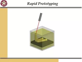
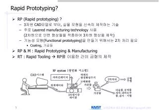
General Procedure for Creating Medical Models RP is a technology that produces models and prototype parts from 3D CAD model data, CT and MRI scan data, and model data created from 3D object digitizing systems • MRI/CT data acquisition • Creation of a CAD model • Conversion of the CAD model to STL format • Slicing the STL file into thin cross-sectional layers • Construction of the model one layer atop another • Cleaning and finishing the model • Preplanning surgery on RP Model and use as a prosthetic and implantation
Partial Volume Effect or Volume Averaging • The DICOM image contains number of pixels. • Pixel value represents the proportional amount of x-ray energy that passes through anatomy and strikes the detector. • The information contained in each pixel is averaged so that one density number (or Hounsfield unit [HU]) is assigned to each pixel. • If an object is smaller than a pixel, its density will be averaged with the information in the remainder of the pixel. • This phenomenon is referred to as the partial volume effect or volume averaging. It results in a less accurate image. • Partial volume effect arises due to matrix size, field of view (FOV), voxel size, Layer Thickness and Interval Thickness.
Partial Volume Effect due to Matrix Size • Generally 256x256, 512x512, 1024x1024 matrix sizes are used. • Based on this matrix size the image is constructed, while tissue size is constant • DICOM image errors depend on length of the square. Because after converting .stl file from this DICOM images, each square is divided into two triangles. These triangles height gives the error of RP model • Example: 512 x 512 mm2 area of the tissue is considered for constructing the image • If selecting 512x512 matrix. In this each square the tissue is selected with 1 mm2 . Here error is 1mm • If selecting 256x256 matrix. In this each square the tissue is selected with 2 mm2. Here error is 2mm • If selecting 1024x1024 matrix in this each square the tissue is selected with 0.5 mm2 from this error is observed 0.5 mm • From the above example to minimize the error we have to choose 512x512 or 1024x1024 matrix size
Partial Volume Effect due to Pixel size HU Selected Area Tissue Area • Partial Volume effect is reduced by decreasing the pixel size • In the RP process the RP model error depends on pixel size because these pixels are divided into two triangles in the “.stl” file .
Partial Volume Effect due to Field of View (FOV): • Field of View (FOV): area of the tissues covered to construct the image is called Field of View (FOV) • Based on this area the image is divided into number of pixels • Field of View (FOV)= Matrix size X Pixel size • Example: Suppose while taking the CT Scan of the mandible height of 10cm, a radiologist considers the full skull height of 30cm. • If the image is constructed in both cases by 512x512 matrix , for 10cm FOV the pixel size assigned is 0.19 mm. similarly for same matrix size for 30cm FOV the pixel size assigned is 0.58 mm. • If Pixel size increases accuracy of the RP model decreases • From the above observation we have to choose less FOV to construct the image in order to capture the required coverage area.
Partial Volume Effect due to Voxel Size • Voxel size: It represents a volume element . Voxel is the volume of pixel size area and X-Ray beam attended (Z – Axis direction) distance or slice thickness. • The voxel is a cube of data. All of the data within the voxel are averaged together to result in one HU. So Voxel size also plays a vital role in partial volume effect. Slice thickness Pixel Volume element
Partial Volume Effect due to Volume Element Size • In the voxel element Z axis–will be longer than either the X or Y dimensions. Therefore, the slice thickness will play an even larger role in volume averaging than matrix size. 2 mm slice thickness voxel element Two 1 mm slice thickness voxel elements
Partial Volume Effect due to Layer Thickness and Interval Thickness • From the above observation to minimize the errors in RP model, we have to choose smallerlayer thickness and interval thickness.
Dumb-bell effect A smaller (or larger) threshold value than the true value ends up adding (subtracting) an additional layer to (from) the original boundary it is called dumb – bell effect.
Method Linear measurements of mandible 3D model Measurements are measured on CATIA
Conclusions • While taking CT image the following parameters are considered to produce good quality RP model • Select 512x512 matrix size to construct the DICOM image • Partial Volume effect is reduced by decreasing the pixel size, selecting smaller volume element and chooseing smaller layer thickness and interval thickness • Choose less FOV to construct the image and capture the required coverage area. • For CT scanning to reduce the Partial volume effect, for a matrix size of 512×512, pixel size being 0.463mm × 0.463 mm, voxel size 0.463mm × 0.463mm × 0.6 mm, layer thickness is 0.6mm and interval thickness is 0.6 mm. similarly to reduce the Dumb-bell effect, the threshold value for bone tissue 1000 HU, in MIMICS software 226 HU. • In this study, it is observed that a dimensional error of ±0.4 mm occurrs by comparing human anatomy and 3D model generated in MIMICS software using DICOM images.
References • Goldman. L. W, “Principles of CT and CT Technology”, Journal of Nuclear Medicine Technology, 2007, vol 35, p.p 115–128. • Mildenberger. P, Eichelbery. M and Martin. E, “Introduction to the DICOM Standard”, European Radiology, 2002, vol 12, P.P 920-927. • Milovanovic. J, Trajanovic. M, “Medical Applications of Rapid Prototyping”, Journal of Mechanical Engineering, 2007, Vol. 5, No 1, P.P 79 – 85. • Tukuru. N, Gowda K. P, Ahmed. S. M and Badami. S, “Rapid Prototype Technique in Medical Field”, Research Journal of Pharmacy and Technology, Oct.-Dec. 2008, Vol 1, P.P 341-344. • Herlin. G, Koppe.M, Béziat. J. L, Gleizal. A, “Rapid prototyping in craniofacial surgery: Using a positioning guide after zygomatic osteotomy - A case report” Journal of Cranio-Maxillo-Facial Surgery, 2011, vol 39, P.P 376 – 379. • Lethaus. B, Poort. L, Bockmann. R, Smeets. R, Tolba. R, Kessler. P, “Additive manufacturing for microvascular reconstruction of the mandible in 20 patients”, Journal of Cranio-Maxillo-Facial Surgery, 2012, vol 40, 43 – 46. • Choi. J.Y, Choi. J. H, Kim N. K, Kim .Y, Lee J.K, “Analysis of errors in medical rapid prototyping models”, International Journal of Oral & Maxillofacial surgery, 2002, vol 31, P.P 23–32. • Winder .J and Bibb. R, “Medical Rapid Prototyping Technologies: State of the Art and Current Limitations for Application in Oral and Maxillofacial Surgery”, American journal of Oral and Maxillofacial Surgery, 2005, vol 63, P.P 1006-1015. • Fischer. C. E. H, Vaandrager. J. M, Zonneveld. F. W, Andersen. B. P, “Precision and accuracy of CT-based measurements of masticatory muscles in patients with hemifacial microsomia”, journal of the International Association of Dentomaxillofacial Radiology, 2004, vol 33, P.P 12–16. • Mallepree. T, Bergers. D, “Accuracy of medical RP models”, Rapid Prototyping Journal, 2009, vol 15, P.P 325–332.
Author Contacts • Manmadhachary .A, • Research Scholar, • Department of Mechanicla Engineering, • National Institute of Technology, • Warangal, Andra Pradesh,India. • E - MAIL:- manmadhachary@yahoo.co.in Thank you for your attention !