Download

1 / 13
130 likes | 275 Views
積體電路設計研究所. 1.5 V large-driving class-AB buffer amplifier with quiescent current control. 指導教授:林志明 老師 學生:賴信吉 Mail: s94662005@mail.ncue.edu.tw. # IEE 2004 9 October 2003 Electronics Letters online no: 20040044 doi: 10.1049/el:20040044

E N D
積體電路設計研究所 1.5 V large-driving class-AB buffer amplifier with quiescent current control 指導教授:林志明 老師 學生:賴信吉 Mail: s94662005@mail.ncue.edu.tw
# IEE 2004 9 October 2003 Electronics Letters online no: 20040044 doi: 10.1049/el:20040044 Chih-Wen Lu and Yen-Chung Huang (Department of Electrical Engineering, National Chi Nan University, 1, University Road, Puli, Nantou Hsien, Taiwan, Republic of China) E-mail: cwlu@ncnu.edu.tw ELECTRONICS LETTERS 8th January 2004 Vol. 40 No. 1
Outline • Introduction • Proposed amplifier • Experimental results • Conclusion • References
Introduction • As the portable equipment is continuously growing and the circuit enters into the system on a chip (SoC) era, there is much demand to develop low-voltage buffer amplifiers. • The buffer achieves a large driving capability by employing two current mirrors, which also control the output quiescent current.
Combination • A folded-cascode differential amplifier(M1–M9). • Two sets of current mirrors (M10–M14 and M15–M19). • M13 and M14 are designed to have the same sizes. • The aspect ratio of M11 is chosen to be slightly smaller than that of M10.
Counterpart • M13,M14→M15,M16 • M12→M17 • Rc1,Cc1→Rc2,Cc2 • M10,M11→M18,M19 • M21→M20
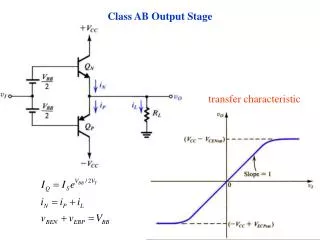
In the stable state, the gate voltage of M10 is equal to that of M11. • This will make M12 be in the triode region. • The gate voltage of M21 will be close to the value of the gate voltage of M14. • The quiescent current of M21 will be controlled by this set of current mirrors.
Experimental results • 0.35 μm CMOS technology. • Active area is 119*257 μm. • With a 1.5 V single power supply and was loaded with a 100 Ω resistor in parallel • with a 150 pF capacitor
Input Output The rise and fall times are 0.4 and 1 μs, respectively. The offset voltage is 8 mV.
The total harmonic distortion is -56 dB. The total static current is 80 μA.
Conclusion • The circuit features a large output swing and low distortion. • A 1.5V buffer amplifier has 80 μA static current, and the rise time of 0.4 μs and fall time of 1 μs under a 100 Ω resistor in parallel with a 150 pF capacitor. • The total harmonic distortion of -56 dB with an output voltage of 1 Vp–p is measured. The offset voltage is 8 mV