Download
1 / 55
580 likes | 698 Views
Explore the foundational components of computer architecture, such as the Arithmetic Logic Unit (ALU) and Control Unit. Learn about logic gates, registers, memory, and the input/output system. Discover how data is processed and manipulated within the CPU.

E N D
Basic Units of Computer Architecture Some of this material can be found in Chapter 3 of Computer Architecture (Carter)
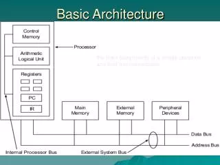
Arithmetic-Logic Unit (ALU) also known as the datapath Control (ROM) Memory (RAM) Input Output Basic Units There are three to five (depending on how you count) basic units that make up a computer Central Processing Unit (CPU) Input/Output (I/O)
Arithmetic/Logic Unit • So much of what goes on inside a computer is just holding of and/or movement of data, but the actual computation (the manipulation of data to generate “new” data) takes place in the ALU. • Because data is represented in binary form (1’s and 0’s), the ALU is mainly comprised of logic gates, circuits made from transistors that take inputs (combinations of highs and lows) and produce outputs (different combinations of highs and lows). • Logic in which the output depends solely on the input is called combinatorial.
Logic Gates and Boolean operators • There is a correspondence between logic gates and Boolean operators • AND: when two or more Boolean expressions are ANDed, both must be true for the combination to be true. • OR: when two or more Boolean expressions are ORed, if either one or the other or both are true, then the combination is true. • NOT: takes one Boolean expression and yields the opposite of it, true false and vice versa. • NAND: equivalent to an AND followed by a NOT • NOR: equivalent to an OR followed by a NOT
ALU Cont. (Registers and Accumulators) • The ALU is not entirely combinatorial, it also has some sequential components, which can temporarily hold information. • These little holding units are known as registers. • The primary registers associated with the ALU go by the name accumulators. • The computer’s “scrap paper”.
Hierarchy of bit holders • An electronic circuit that holds a single bit (a 1 or a 0) is called a flip-flop. • A small collection of flip-flops (8 or 16 or 32, etc.) is called a register. • A counter is a kind of register that in addition to holding bit values can increment the number they represent. • A shift register can hold a number as well as “shift” it. • 00101101 • 01011010 • 10110100, etc. • A collection of registers along with a way to address (select out) a particular register is called memory.
Control Unit • Control is responsible for determining what action is to be performed on what data. • If the action is a calculation, then control will deliver the necessary data to the ALU, inform the ALU, what particular action is to be performed, and then directs the output to the appropriate location.
Control Cont. • All of the other units of a computer have “control inputs” that determine whether or not they are active and what particular action they will perform (if they can do more than one thing). • Control takes code down to this lowest level of making the appropriate control inputs high or low, active or inactive. • Not all devices are active when the control input is high, some devices are “active low.”
Control is ROM • At a high level, instructions may be arranged in new and different orders (this after all is what makes the computer programmable). But at the low level the control sequences for a given instruction do not change. • Control sequences are thus made of Read Only Memory (ROM) which are reprogrammed rarely if at all.
Memory • Memory consists of circuits whose primary purpose is to hold information, but only temporarily. • Memory holds the data that the processor has just acted on, is acting on or will soon act on. • When we use the term memory, we usually mean Random Access Memory (RAM).
Memory Memory is collection of holding cells (like registers). Each cell has an address.
Random Access • The data in any holding cell can be accessed immediately for purposes of reading or writing by supplying its address. • Any random site can be “immediately” accessed. • As opposed to sequential access in which one must pass through all intermediate data between one’s current location and the next desired location. • VCR tapes are sequential; • DVDs are random access (they support scene selection and don’t have to be rewound).
Memory versus Storage • Memory is a temporary holding place that interacts fairly directly with the processor. • Memory is volatile, the holding of the information requires power. No power, no data held. • Longer term holding of data not currently being processed is done in storage (hard disks, floppy disks, CDs). • In this “basic units” picture of the computer storage belongs to the Input/Output unit.
Input / Output • The Input unit allows programs and data to be entered into the computer. • The Output unit allows the results of processing to be exported to the outside world or other devices or saved to be used later. • This other device may be in the same case as the processor, but it is output as far as the processor and memory are concerned. Thus the hard drive is both an input and an output device in this picture.
Charles Babbage • In the early 1800’s Charles Babbagedesigned two machines: first the Difference Engineand then the Analytical Enginethat were mechanical machines capable of performing calculations. • The Difference Engine, most (but not all) of which was built in Babbage’s time, was a special purpose machine (i.e. it could only do particular calculations). • The Analytical Engine, which was designed but not built in Babbage’s time, was more ambitious in that it was programmable. Who am I? What am I doing here?
Babbage’s “Mill” Built later based on Babbage’s specifications. https://www.youtube.com/watch?v=be1EM3gQkAY
Babbage’s design • Babbage’s design had the basic units we have been describing. • He conceived of it as having four components: • the store (memory) • the mill (computational unit, control + ALU) • the input section (punched card reader) • the output section (punched and printed output).
Babbage (Cont.) • Babbage’s engines were entirely mechanical and were comprised of gears and cogs and such. • The store held 1000 words of 50 decimal digits used to hold variables and results. • The mill (processor) could take data from the store, add, subtract, multiply or divide them, and return the answer to the store.
Babbage Input and Output • The engine’s input was from punched cards. • Punch cards started being used in industry (weaving) since the early 1800’s. They disappeared (mostly) in the 1980’s. • The data input was not simply data from the calculations but also data for instructions, making the engine programmable. • Instructions included being able to test whether a number was positive or negative (an if). • The engine’s output could be punched into a copper engraver's plate producing a hardcopy.
Fast forward a hundred years • In the 1940’s the Electronic Numerical Integrator And Computer (ENIAC) was built at the Moore School of the University of Pennsylvania. • It was completed in 1946 at the Moore School of the University of Pennsylvania. • The two driving forces behind it were John W. Mauchly and J. Presper Eckert. • There were other computers built during WWII notably the one developed at Bletchley Park, UK to aid in their code breaking mission and that developed by Konrad Zuse in Germany. Who am I? What am I doing here?
ENIAC • The ENIAC consisted of 17,480 vacuum tubes operating at 100,000 pulses per second. • Think of a vacuum tube as a “souped up light bulb.” • Vacuum tubes play the same role that transistors do in modern computers (one can use them to “realize” logic gates) • The switch from vacuum tubes to transistors marked a dramatic shift in computer size and speed. People talk about the computers as belonging to different “generations.” Moving to transistors is a generational shift. • The Pentium 4 processor introduced in 2000 had 42,000,000 transistors. The Itanium 2 in 2004 had 592,000,000 transistors. The size and power requirements of vacuum tubes would have prohibited these kind of numbers. We are now in the billions of transistors.
Programming • One drawback to the ENIAC was the way it was programmed — with wires. • A new program required rewiring. • Mauchly, Eckert and John von Neumann discussed designs of future computers (like EDVAC) in which the programs (instructions) would be stored in the computer’s memory.
Von Neumann Architecture • John von Neumann was a consultant to the ENIAC project. The team discussed changing the way computers were programmed. Von Neumann publicized and popularized these ideas. • The instructions could be converted into numbers and placed in memory along with the data. This is known as the stored program concept. • The combination of the basic units (ALU, control, memory, input and output) and the stored program concept give one the “von Neumann architecture.”
Harvard architecture • In the von Neumann architecture, the instructions and data are held in the same memory. • A variation on this, known as the Harvard architecture, has the instructions and data held in separate memories. • A more modern variation on the Harvard architecture is to have the data and instructions in the same main memory but to place them in separate caches.
Micro-code (note: micro, not macro) • What’s held in the memory is a low-level (assembly or machine code) instruction which may have resulted when some high-level language program was compiled. • Below that is micro-code, the instructions at the lowest level, those control signals fed directly to the hardware. • Any higher-level instructions (including assembly) must ultimately be converted to a lower level by control. • A single machine-language instruction (like Load Accumulator A) typically consists of several micro-code instructions. • Similarly a single high level instruction (such as principle = principle*(1+interestRate) often consists of several assembly level instructions.
Where is microcode stored? • It used to literally be wired in (hence the term “hard wired”). • Typically it stored in ROM. • If the code is stored in EEPROM, it can be changed; this is known as microprogramming. • EEPROM: Electrically Erasable Programmable ROM • Flash ROM is a type of EEPROM • But this is something one does on a rare occasion • Sometimes referred to as “firmware,” an intermediate between software and hardware.
Machine language • Machine language is a level above micro-code • The instructions are numbers, which really are the addresses of the micro-code instruction in ROM. • Machine language is typically machine dependent. The locations in ROM of the microcode vary from one make of a computer to the next. • A mnemonic version of machine language is called assembly language.
Getting down to hardware’s level • High-level programs are translated into assembly language or machine language by a compiler. Assembly language programs are translated into machine language by an assembler. • Each processor has its own unique machine language. Thus code must be rewritten or at least recompiled to run on different processor (different hardware).
A simple design • Next we will show a computer design. • It uses a very basic “bus architecture.” • A bus is a shared path used to transmit and receive information.
Bus Keyboard encoder Input port 1 Accumulator Flags ALU Input port 2 Prog. counter TMP Mem.Add.Reg. B Memory C MDR Output port 3 Display Instr. Reg. Output port 4 Control
One Bus, Two Bus • In this very primitive architecture, there is only one bus. • Recall that memory can be thought of as values located at addresses. Here the same bus is used for both data (values) and addresses. • This will make accessing memory (reading or writing) a two-step process – deal with the address, then deal with the data. • Dealing with memory is always a two step process, but in this architecture the one and only bus is tied up for both steps (no parallelism or pipelining allowed). • That is not the usual case. Most architectures have an address bus and a data bus.
Keyboard encoder: converts key pressed into corresponding string of bits (ASCII) Input port 1: where keyboard data is entered, usually contains some memory (a buffer) where data is held until the processor is ready for it. Input port 2: where non-keyboard data is entered. Input ports
The program counter points to the current line of the program (which is stored in memory) This design shows arrows connecting the “PC” to and from the bus, why? Sometimes the next instruction to be executed is not the next line of code in memory, such as If Loops Subroutines, functions, etc. Program counter
MAR (Memory Address Register) holds the address of the memory location being read from or written to Not necessarily same as program counter Memory (RAM): the place where data and instructions are stored MDR (Memory Data Register) holds the data that is being read from or written to memory Bi-directional connection to bus for reading and writing MAR, MDR and Memory
Instruction registerholds the instruction that is currently being executed. A given line of assembly or machine language code involves several micro-code instructions, the instruction register holds onto the instruction until all of the micro-instruction steps are completed. It plays a role somewhat like the MAR but for ROM instead of RAM Instruction Register
Executes the program at the lowest level. Sends signals to the control pins of all the devices involved. These lowest-level instructions are in ROM Each assembly-level instruction has a numerical counterpart (machine language); the numerical counterpart is the address of the microcode for that instruction stored in ROM. Not shown, controller connects to everything Controller/Sequencer
Accumulator: register used in conjunction with the ALU Data upon which arithmetic or logic operations will eventually be performed is stored here; also the results of these are stored here. ALU (Arithmetic Logic Unit) where operations that change the data (as opposed to just moving it around) are done. Accumulator and ALU
Flags are output from the ALU that are distinct from data (data output goes to Acc. A) For example, A carry from an addition An indication of overflow These are needed for program control or to indicate possible errors The result of a logical comparison (<, >, =) These are needed for control (ifs, loops, etc) Flags
TMP is the other register used in conjunction with the ALU; the distinction is that answers are generally sent to Accumulator A B and C are additional registers used for holding data temporarily They allow additional flexibility and reduce the amount that must be written to memory. TMP, B and C
Output porta connection to the “outside world” Usually includes a buffer This design has one for displayed output and a second for other output (e.g. storage) Output ports
Let us now examine the steps involved in the assembly (machine language) instruction Load Accumulator A. Micro-code