Download
1 / 36
420 likes | 1.13k Views
Tolerancing. Chapter 10. Objectives. Describe nominal size, tolerance, limits, and allowance of two mating parts Identify a clearance fit, interference fit, and transition fit Describe the basic hole and basic shaft systems. Objectives (cont.).

E N D
Tolerancing Chapter 10
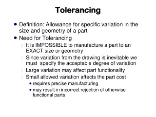
Objectives • Describe nominal size, tolerance, limits, and allowance of two mating parts • Identify a clearance fit, interference fit, and transition fit • Describe the basic hole and basic shaft systems
Objectives (cont.) • Dimension mating parts using limit dimensions, unilateral tolerances, and bilateral tolerances • Describe the classes of fit and give examples of each • Draw geometric tolerancing symbols • Specify geometric tolerances
Understanding Tolerance • Tolerancing is an extension of dimensioning • It allows you to specify a range of accuracy for every feature of a product so the parts will fit together and function properly when assembled
Understanding Tolerance • To provide tolerances in CAD, you must: • Understand the fit required between mating parts • Have a clear picture of how inspection measurements are performed • Be able to apply tolerance symbols to a drawing
Tolerance • Tolerance is the total amount a specific dimension is permitted to vary • Use generous tolerances when possible because increased precision makes parts more expensive to manufacture
Quality Control • Large batches of parts may use statistical methods to control quality where a sample of parts are inspected • Specific tolerances are based on the part’s function and fit
Variations in Form • Acceptable parts must not extend beyond boundary limits
Implied 90 Degree Angles • When lines intersect on a drawing at angles of 90 degrees, it is customary not to dimension the angle • Implied 90 degree angles have the same general tolerances applied to them as any other angles covered by a general note
Fits Between Mating Parts • Fit is the term for the range of tightness or looseness resulting from the allowances and tolerances in mating parts
Definitions for Size Designation • Nominal size – used for general identification and usually expressed in decimals • Basic size (basic dimension) – the theoretically exact size from which limits of size are determined
Definitions for Size Designation • Actual size – the measured size of a finished part • Allowance – the minimum clearance or maximum interference specified to achieve a fit between two mating parts
Basic Hole System • Toleranced dimensions are commonly determined using the basic hole system in which the minimum hole size is taken as the basic size
Basic Shaft System • In this system, the maximum shaft is taken as the basic size and is used only in specific circumstances
Specifying Tolerances • The primary ways to indicate tolerances in a drawing are: • A general tolerance note • A note providing a tolerance for a specific dimension • A reference on the drawing to another document that specifies the required tolerances
Specifying Tolerances • (cont.) • Adding limit tolerances to dimensions • Adding direct plus/minus tolerances to dimensions • Geometric tolerances
Metric System of Tolerances and Fits • The preceding material on limits and fits applies to both systems of measurement • The ISO has a system of preferred metric limits and fits • The system is specified for holes, cylinders, and shafts and has similar definitions of terms
Geometric Tolerancing • Geometric tolerances state the maximum allowable variations of a form or its position from the perfect geometry implied in the drawing • The term “geometric” refers to forms such as planes, cylinders, squares, etc.
Geometric Tolerancing • Tolerances of form and position (or location) control such characteristics as: • Straightness • Flatness • Parallelism • Perpendicularity (squareness) • Concentricity • Roundness • Angular displacement, etc.
Datum Surfaces and Features • Datum surfaces and features are used as references to control other features
Maximum Material Condition • Maximum material condition (MMC) means that a feature of a finished product contains the maximum amount of material permitted by the toleranced dimensions for that feature
Tolerances of Angles • Bilateral tolerances have traditionally been given on angles
Using Geometric Dimensioning and Tolerancing • Geometric dimensioning and tolerancing (GDT) considers an individual part’s dimensions and tolerances and that part’s relation to its related parts • GDT also simplifies the inspection process
Using Geometric Dimensioning and Tolerancing • Applying GDT principles requires: • Defining the part’s functions • Listing the functions by priority • Defining the datum reference frame • Control selection • Calculating tolerances