Download
1 / 26

E N D
The Electromagnetic Calorimeter for the AMS 02 experiment on the ISSF. Cervelli a, G. Chen c, H. Chen c, G. Coignet d, S. Di Falco a, E. Falchini b, L. Girard d, C. Goy d, R. Kossakowsky d, T. Lomtadze a, Z. Liu c, Y. Lu c, P. Maestrob, P.S. Marrocchesi b, R. Paoletti b, F. Pilo b, S. Lees-Rosier d, N. Turini b, G. Valle b, J.P. Vialle d, G. Venanzoni a, Z. Yu c, H. Zhuang ca) Istituto Nazionale di Fisica Nucleare INFN-Pisa, Italyb) University of Siena-INFN Gruppo Collegato, Italy c) Institute of High Energy Physics-IHEP Beijing, Chinad) Laboratoire d’Annecy de Physique des Particules-LAPP, France
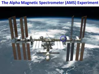
Alpha Magnetic Spectrometer AMS 02 is a large acceptance (0.5 m2·sr) space-borne spectrometer to be installed on the ISS for 3 years. AMS 02 Physics: • Search for Nuclear Antimatter (anti-He,C) @ 10-9 sensitivity • Search for SUSY Dark Matter (p-, e+, g spectra) • Astrophysics: light isotopes, 3He, 4He, B/C , 9Be/10Be spectra • VHE g astronomy
AMS 02 –The Detector • Superconducting magnet(0.85 T·m2) • Time of Flight - L1 Trigger, dE/dx , Dt<150 ps • TRD - 20 layers of drift tubes in polypropilene - e/h rejection O(102) up to 300 GeV • TRACKER • 8 planes of double-sided Si microstrips • DP/P=2% @ 1 GeV, dx=10 mm • RICH - Aerogel+drift space+PMTs - High precision (10-3) b measurement • 3D sampling ECAL
Eletromagnetic CALorimeter • High granularity (Pb-SciFi) sampling calorimeter • Active detector -dimensions: 658658162 mm3 -weight: 492 Kg -built out of 9 superlayers -total rad. length X0: 17 • PMTs -Hamamatsu R7600-00-M4 -total number: 324
ECAL superlayer • 1 SuperLayer: 11 grooved Pb foils (1mm thick) interleaved with layers of SciFi (=1mm) glued by means of an epoxy resin • Superlayers alternatively oriented along orthogonal directions • SciFi read-out on one side only • Light guide geometry fits the area of the 4 cathodes of a PMT • Read-out granularity: 99 mm2 • 1296 cells (72 per layer)
ECAL goals • Measurement of the total energy of e.m. showers from 1 GeV to 1 TeV • e/h discrimination from 10 GeV to 1 TeV with a rejection power 103-104 • 3D imaging of the e.m. and hadronic showers development e.m. reconstruction of the shower direction and impact point on ECAL angular resolution < 1° @ E > 50 GeV hadronic lateral shower image improves proton rejection
Oct. 2001 Test Beam Setup • ECAL equipped with a total of 36 PMTs: Effective active area: 7272 mm2 (8 cells/layer instrumented) • ECAL read-out electronics: • No front-end sampling electronics • Cathode signals into CAMAC gated charge integrating (12 bit) ADCs • Beam particles: • - @ 100 GeV • e- @ 3,5,8,10,15,20,30,50,70,100 GeV • Beam particles trigger: 3-fold coincidence of scintillation counters aligned along the beam line
Oct. 2001 Test Beam Data Analysis • PMTs equalization method • e.m. shower profile reconstruction • Radiation length measurement • Energy linearity measurement (with and without leakage correction) • Energy resolution measurement
PMTs equalization • Gain differences: - among the 36 PMTs - among the 4 pixels of each PMT (up to a factor 2 as from Hamamatsu specs) • Fluctuations in light transmission among the light guides. • Difficulty to equalize cells using mips. The average mip signal in almost all ECAL cells was not well separated from the pedestal (light collection system+FE electronics: not the final version). Need for an equalization procedure based on electrons runs analysis.
Inclusive energy distributions of equalized cells Cell 4 –Layer 4 Cell 5-Layer 4 Cell 6-Layer 4 ADC ADC ADC Beam spot diameter is about 3 cm 3 cells/layer are illuminated & expected to show similar energy distributions (if the cells are roughly equalized). P. Maestro University of Siena-INFN CALOR2002 March 25-29,2002
Inclusive energy distributions of not-equalized cells Cell 4 –Layer 5 Cell 5-Layer 5 Cell 6-Layer 5 ADC ADC ADC The response difference among cells were found to be up to a factor 2, due to PMTs gain differences and light losses in the optical couplings. P. Maestro University of Siena-INFN CALOR2002 March 25-29,2002
Layer energy distributions before equalization Layer 4 • Layers with roughly equalized cells show a gaussian shape energy distribution. • Layers with not-equalized cells have broad energy distributions with the possible presence of two peaks. ADC Layer 5 ADC
PMTs equalization procedure • Groups of events with shower axis crossing different cells can be separated by a selection on the COG position in each layer. • Each group contribution to the inclusive layer energy distribution can be evaluated and adjusted at a common mean value, chosen according to the longitudinal G fit. • Scanning the ECAL surface with the beam spot, the procedure can be iterated to equalize other cells.
Selection on the COG position Layer 5 – COG cuts Layer 4 – COG cuts cell cell Layer 5 - Energy distribution Layer 4 - Energy distribution ADC ADC
Layer energy distributions before & after equalization Layer 4 Layer 4 ADC ADC Layer 5 Layer 5 ADC ADC
Radiation length (X0) measurement • Fit of the e.m. shower longitudinal profile: • Position of the shower maximum: • X0 can be measured from the relation:
TMAX vs. log(E) X0= (9,6 0.3) mm ECAL ~ 16.8 X0
Energy linearity and resolution • The electrons runs @ 3,5,8,10,15 GeV (no longitudinal leakage expected) have been used to calibrate the calorimeter (i.e.:conversion factor ADCGeV). • Leakage correction in higher beam energy runs has been applied using the E0 parameter from the average longitudinal profile fit. • Energy resolution fit
Linearity (no leakage correction applied) • ECAL shows good linearity at beam energies up to 20 GeV (no appreciable long. leakage) • Long. leakage: 15% @ 70 GeV 20% @ 100 GeV
Linearity (leakage correction applied) • Good reconstructed linearity up to 50 GeV • Small deviations at higher beam energies: 2% @ 70 GeV 4.5% @100 GeV • Non linearity attributed to the incomplete coverage of the lateral development of the shower (limited number of ECAL cells instrumented)
Conclusions • A full scale prototype of AMS 02 ECAL was successfully tested at CERN. • Feasibility of ECAL equalization using electrons was demonstrated • Good linearity and capability of longitudinal leakage reconstruction • Energy resolution as expected from MC simulations • Radiation length in agreement with the design specifications (ECAL total thickness ~17 X0) • A quantitative study of proton rejection was not possible due to the small statistics collected with hadrons beams and the limited lateral detector coverage. The rejection will be measured in a future test beam.