Download
1 / 8
80 likes | 201 Views
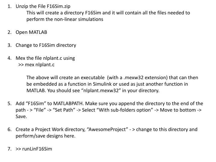
Unzip the File F16Sim.zip This will create a directory F16Sim and it will contain all the files needed to perform the non-linear simulations Open MATLAB Change to F16Sim directory Mex the file nlplant.c using >> mex nlplant.c

E N D
Unzip the File F16Sim.zip • This will create a directory F16Sim and it will contain all the files needed to perform the non-linear simulations • Open MATLAB • Change to F16Sim directory • Mex the file nlplant.c using • >> mexnlplant.c • The above will create an executable (with a .mexw32 extension) that can then be embedded as a function in Simulink or used as just another function in MATLAB. You should see “nlplant.mexw32” in your directory. • Add “F16Sim” to MATLABPATH. Make sure you append the directory to the end of the path - > “File” -> “Set Path” -> Select “With sub-folders option” -> Move to bottom -> Save. • Create a Project Work directory, “AwesomeProject” - > change to this directory and perform/save designs here. • >> runLinF16Sim
The following list of commands will create the transfer functions for • Altitude – elevator, b) bank angle – aileron, c) pitch angle – elevator and d) yaw angle – rudder. • After you are done with runLINF16sim, • sys = ss(A,B,C,D); % Creates the large state space system object • systf = tf(sys); % Converts the SS object to a Transfer Function object • syshde = minreal(systf(3,2)); % Pulls out the Altitude – Elevator TF • sysphida = minreal(systf(4,3)); % Pulls out the Bank – Aileron TF • systhede = minreal(systf(5,2)); % Pulls out the Pitch – Elevator TF • syspsidr = minreal(systf(6,4)); % Pulls out the Yaw – Rudder TF • % Save into a file called design Project • save designProject sys systfsysphidasysthedesyspsidrsyshde • Example: • Pitch-Elevator Transfer function: • -154.5 s^2 - 114.6 s - 1.452 • ------------------------------------------------------------------------------- • s^5 + 21.99 s^4 + 38.67 s^3 + 50.51 s^2 + 0.684 s + 0.3423
Example (contd.) • Pitch-Elevator Transfer function: systhede • -154.5 s^2 - 114.6 s - 1.452 • ------------------------------------------------------------------------------- • s^5 + 21.99 s^4 + 38.67 s^3 + 50.51 s^2 + 0.684 s + 0.3423 • >> damp(systhede) • Eigenvalue Damping Freq. (rad/s) • i) -4.20e-003 + 8.26e-002i 5.08e-002 8.27e-002 • ii) -4.20e-003 - 8.26e-002i 5.08e-002 8.27e-002 • iii) -8.91e-001 + 1.30e+000i 5.66e-001 1.57e+000 • iv) -8.91e-001 - 1.30e+000i 5.66e-001 1.57e+000 • v) -2.02e+001 1.00e+000 2.02e+001 • The last eigenvalue corresponds to the actuator. • (i) and (ii) are characterized by low frequency and low damping (stable) and correspond to the long period (Phugoid) mode. • (iii) and (iv) correspond to the short period mode. • DESIGN REQUIREMENT: Increase short period damping to 0.707
See if the DESIGN REQUIREMENT can be met using a simple proportional gain (K). • Perform this analysis using the Root Locus method we just discussed in class. • Plot the step response for a unit elevator deflection using ‘systhede’ with and without the control element. • Can you place the closed loop poles (short period only) such that they have a damping of 0.707 and frequency of 2 rad/s? • What happens to the other roots if you meet the above objective? • Document your analysis. • For those who have unstable systhede, you need to find a way to stabilize the system as well as satisfy the DESIGN REQUIREMENT.
The following requirements can be used as a guideline for your controller design for the project • Longitudinal Dynamics • Stable Phugoid (Long period) • Short period dynamics • Damping ratio between 0.5 – 0.85 • Frequency between 2.0 – 5.0 rad/s • Lateral-Directional Dynamics • Stable roll subsidence • Stable spiral • Stable Dutch Roll • Damping ratio – at least 0.3 • Frequency – at least 1.5 rad/s • Real part of the dutch roll poles – at least 0.35
Each team will design the following autopilots, • Pitch displacement autopilot (consider ) • Altitude hold autopilot (consider ) • hc is the commanded altitude • It is desirable that the achieved altitude has less than 5 percent overshoot . • Roll autopilot to achieve a desired bank angle and a yaw damper to improve the Dutch Roll Performance • HINTS: • Good pitch displacement can be achieved by using a PD element in the feedback path and a PI element in the forward path (after the summing junction). • Once the pitch displacement autopilot is done, consider altitude hold autopilot with the pitch loop closed. • For the Yaw-Damper you may use in the feedback pathand a simple gain after the summing junction. Find appropriate values for T and the Gain to get desirable properties.
PROJECT REPORT Cover page with names of the team members and signatures. The main body of the text should be formatted 11 pt, Times New Roman with 1 inch margin on all sides. The following items must be summarized – Flight condition at with the design was performed, Design requirements, Transfer functions employed for design, Analysis of the transfer functions, Specific actions taken to improve performance, Choice of control elements (why did you choose those elements), Final controller transfer functions, Simulation results. Provide details of the contributions from each team member when you are organizing the report. For simulation, you will build a Simulink diagram using the Complete System with 4 control inputs (Thrust, Elevator, Aileron, Rudder) and 12 outputs (North, East, Down, Roll, Pitch, Yaw, Velocity, AoA, AoS, Roll Rate, Pitch Rate, Yaw Rate). Fix the Controls and all the other States at the trim values obtained from earlier work. Add the control elements to this and simulate the system. (See Figure)