Download
1 / 43
430 likes | 666 Views
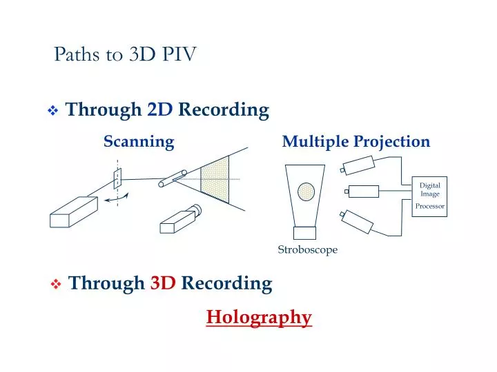
Through 2D Recording. Multiple Projection. Scanning. Digital Image Processor. Through 3D Recording. Stroboscope. Paths to 3D PIV. Holography. Recording. Reconstruction. Laser Pulse. Laser Beam. 8ns. CCD. Interrogation camera. Hologram. 3D flow seeded with particles.

E N D
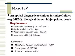
Through 2D Recording Multiple Projection Scanning Digital Image Processor • Through 3D Recording Stroboscope Paths to 3D PIV Holography
Recording Reconstruction Laser Pulse Laser Beam 8ns CCD Interrogation camera Hologram 3D flow seeded with particles Double Exposure Holocine (time resolved) t2 t2+ Dt t1 t1+ Dt t2 t3 t1 Principle of HPIV Displacement Velocity
Advantage of holography • True 3D imaging • Instantaneous Volumetric • High Information Capacity(106 - 109 Particles) • Real-Time Recording but Off-line Data Transfer & Processing
How to get true 3D imaging? Phase Preservation O=Oexp[i(f-wt)] or: O=Osin(f-wt) How to record f? Any light sensitive media records intensity I=|O|2 =O2 Need to “encode” phase finto some intensity modulation
Encoding Phase -- Use interference of coherent light! E= R+ O Reference wave Object wave where R = R exp[i(j-wt)] , O=Oexp[i(f-wt)] Recorded Intensity: I=|R+O|2 = R2 + O2 +2ROsin(f-j)
0 x q z B e c n e r e Hologram f e R Recording y Virtual Image 0 x Real Image q m a z Object e B e c n e r e f e m R Hologram a e Reconstruction Principle of Holography O I =|R+O|2= R2 + O2 +2ROsin(f-j) R I =(R+O)(R+O)* = R2 + O2 + R*O+RO* O* T ~ R2 + O2 + R*O+RO* Usually R= exp(-iwt) T ~ 1+ O2 + O + O* O
Experimental Demonstration Reference beam, object beam Virtual, real image *Transmission or Reflection Hologram? Setup Considerations: Coherence length vs. path length difference Exposure energy: In the linear range R:O ratio
Transmission or Reflection Hologram Reflection hologram created by 2 plane waves traveling towards opposite sides (Volume Hologram) Transmission hologram created by 2 plane waves traveling towards the same side
Reflection Hologram Bragg Condition 2dsinq=ml
Reference wave LASER Object wave Viral Image Real Image LASER In-line (Gabor) Holography Traditional for particle fields • Simple geometry • Low coherence & energy requirement • Speckle noise (limit seeding density & seeding depth) • Large depth of focus • (practically only 2D vectors)
Speckle Noise (in-line hologram) Ok= S ok= Skexp(ifk) : Random Walk Reconstruction field of an in-line hologram for an ensemble of particles: B + S ok+ S o*k Type-I speckle -- interference between B and the scattered waves Major Source of Speckle Type-II speckle -- self-interference of the scattered waves.
Speckle noise: decrease Signal-to-Noise Ratio 40 particles /mm3 6 particles /mm3 1 particle /mm3
In-Line HPIV: • Simple Geometry • Lower Coherence Required • Intrinsic Speckle Noise • Lower Seeding Density Virtual Hologram Real Hologram Image Image Reference Reference Beam Beam Reconstruction Recording In-line HPIV Virtual Image Reference Real Reference Beam Image Beam Hologram Illuminating Beam Hologram Recording Reconstruction Off-axis HPIV Off-Axis Holography as Solution Off-axis HPIV: • Higher SNR • Higher Seeding Density • Complex Geometry • Higher Coherence Required
IROV - In-line Recording Off-axis Viewing Holography • IROV: Use side scattering • Suppresses speckle noise • Reduces image depth of focus Making In-line based HPIV feasible Meng & Hussain (1995): Appl. Opt. 34, 1827
IROV Experimental Setup Recording Reconstruction
Use of High-Frequency Fringes on In-Line Holograms • Negligible influence of forward scattering: Since |OL| << |R|, • IL << I sig
IROV suppresses speckle noise Reconstruction field of an in-line hologram for an ensemble of particles: B + S ok+ S o*k • Completely avoids type-I speckle • greatly reduces type-II speckle Off-axis Viewing: receives onlyS o*k
Improved SNR by IROV In-line Viewed IROV
+100 mm In focus -100 mm Reduction of Depth of Focus by IROV In-line: Fraunhofer diffraction 0 degree 20 degree
IROV Data Processing: Genetic Algorithm Particle Pairing Interrogation Cell 4’ 3’ 5’ 3 4 2’ 2 6’ 5 1’ 1 7’ 6 7 • Low density requires intelligent pairing • GA searches large solution space
Genetic Algorithm Particle Pairing
Large solution space Why Genetic Algorithm? Many possibilities to pair particles Need to numerate and filter • Conventional searching methods • Computation intensive • Difficult to incorporate intelligence • Time consuming • Genetic Algorithm • Efficient in searching large space • Built-in intelligence to follow fluid dynamics • Fast and inherent parallel processing speed
Two Approaches of HPIV Developed at LFD Off-axis HPIV high-end In-line (IROV) HPIV low-cost
Dual-Reference Off-Axis Technique • High Seeding Density Allowed • Small Depth of Focus • Image Separation Removes • Direction Ambiguity • Complex Optical Geometry • High Energy Laser Required • High Coherence of Beam • Needed
Concise Cross Correlation(CCC) Algorithm • Matching by particle groups • Uses particle centroids only • Group shifting for matching • Decomposition of operation • Low data volume / high compression rate • High-speed processing
Phase-Locked Vortex Side View Top View
Vorticity Iso-surface To be re-made
Vortab Flow: HPIV Measurement Result • Amount of Data: 400,000 Vectors • Mean Velocity: 16.67 cm/sec.
Hologram captures 3D instantly HPIV = 3D Information Transfer & Processing Turbulent Flow Field Flow Field Reconstruction Fundamental Challenges • 3D Signal Decoding • Complex Flow Mapping • Large DataQuantity • User-friendly?
Holographic Flow Visualization a Tool for Studying 3D Coherent Structures and Instabilities Kansas State University, ISSI, Wright Laboratory, WP/AFB
Off-Axis HFV of Vortex Flame (c) (b) (a) Holographic Images of Three Vortex-Flame Systems Photographed from Two Angles (a) or Using Two Magnifications (b and c).
IROV HFV of Turbulent Milk Drop Holographic Images of A Milk Drop Undergoing Bag Instability (a, b) Holographic Images of A Turbulent Milk Drop (a) and Its Downstream Breakdown (b, c)
Naturally, HPIV is an ideal diagnostic tool for studying particulate phase - 3D and dynamically