Download
1 / 6
70 likes | 295 Views
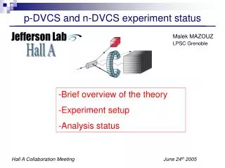
DVCS and GMp Symbiosis. A View from the DVCS Collaboration Charles Hyde. Three models:. Independence GMp installs and runs first ~1 PAC month Full operation of both HRS for GMp , no Luminosity limits from DVCS One month shutdown for DVCS installation DVCS runs ~3 PAC months

E N D
DVCS and GMpSymbiosis A View from the DVCS Collaboration Charles Hyde
Three models: • Independence • GMp installs and runs first ~1 PAC month • Full operation of both HRS for GMp, no Luminosity limits from DVCS • One month shutdown for DVCS installation • DVCS runs ~3 PAC months • No modification to scattering chamber needed • Cooperation • GMp and DVCS install together (except DVCS Calo.) • GMp runs independently • Restrictions on HRS angles from vacuum chamber and DVCS stand • Restrictions on HRS movement from DVCS cables and stand, • HRS movement needs manual assistance • One week shutdown to install DVCS Calo. • DVCS runs ~3 PAC months • GMp acquires parasitic data in HRS-R at large angles. • Symbiosis • GMp and DVCS fully install together • GMp and DVCS running is interlaced (circa weekly) • Maximum luminosity is 25μA × 15 cm LH2 (radiation limit for DVCS Calo.) • Beam in Compton Chicane • Restrictions on HRS angles and movement • GMp acquires “unlimited” parasitic data in wide angle HRS-R • Luminosity is correlated with beam energy: 1037 @ 6.6 GeV, of 10•1037 @ 11 GeV • GMp angles < 40° only accessible with HRS-L • DVCS Calo parked in “safe mode” at 5.5 m from target at 15°
DVCS Cabling Spectrometers movement must be monitored in the Hall 220 RG-213 cables DVCS cables must be moved by hand with HRS-L movement (multi-person effort)
Angle Restrictions(Approximate, to be revised) • Minimum (central) HRS—DVCS-Calo opening angle: 25° (limited by DVCS-Calo stand) • q(HRS-L)–q(DVCS-Calo) ≥ 28.7° • HRS-L ≥ 19° with DVCS-Calo @ –9.7° • q(DVCS-Calo)–q(HRS-R) ≥ 34.5° • |HRS-R| ≥ 49° with DVCS-Calo @ –14.5° • Restrictions of the common Scattering Chamber design • HRS-L ≤ 46° • HRS-R: 33°—80°
Scattering Chamber • HRS-R (central angles) • 49°—80° w/ DVCS Calo @ 14.5° DVCS Calo • HRS-L • 12.5°—46° (central angles) • 14.5° min w/ Calo @ 14.5°