Download
1 / 36
360 likes | 444 Views
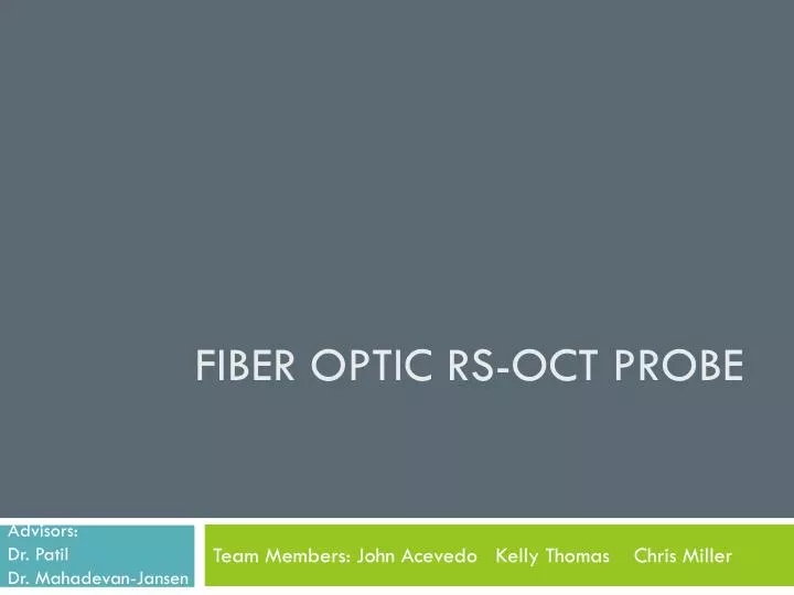
Fiber Optic RS-OCT probe. Advisors: Dr. Patil Dr. Mahadevan-Jansen. Team Members: John Acevedo Kelly Thomas Chris Miller. Problem Statement. Develop a handheld device that can optically detect cancer in a timely manner. Background. Raman Spectroscopy (RS)

E N D
Fiber Optic RS-OCT probe Advisors: Dr. Patil Dr. Mahadevan-Jansen Team Members: John Acevedo Kelly Thomas Chris Miller
Problem Statement • Develop a handheld device that can optically detect cancer in a timely manner
Background • Raman Spectroscopy (RS) • Optical Coherence Tomography (OCT) • RS-OCT • Current probe
Background • Raman Spectroscopy (RS) • Optical Coherence Tomography (OCT) • RS-OCT • Current probe
Raman Spectroscopy • Inelastic scattering (Stokes and Anti-Stokes) • Occurs 1 in 10 million compared to elastic • Frequency of light scattered from a molecule dependent on structural characteristics of molecular bonds • Able to determine malignant from non-malignant tissue • Gives no spatial information n0 n1 Raman Shift (cm-1) = f ( ) – f ( )
Background • Raman Spectroscopy • Optical Coherence Tomography • RS-OCT • Current probe
Optical Coherence Tomography (OCT) • Sensitivity to microstructural features of disease • Measures tissue reflectivity as function of depth • Detects elastic scattering • Ability to image over transverse areas of tissue of greater than 5mm • Micron scale resolution (>25µm) • Real-time speed
Background • Raman Spectroscopy • Optical Coherence Tomography • RS-OCT • Current probe
RS and OCT are complimentary Raman Spectroscopy • Strengths • Biochemical Specificity • Limitations • No spatial Information • Susceptible to sampling error Optical Coherence Tomography • Strengths • Micron-scale structural resolution • Real-time imaging speeds • Limitations • Insensitive to tissue biochemical composition
Reason for fiber optic RS-OCT probe • Improve detection and diagnosis of cancer • Hand held device will facilitate the use RS-OCT probe • A fiber optic probe will decrease the size of the current probe • Potential endoscopic use, non-invasive • Cost effective
Background • Raman Spectroscopy • Optical Coherence Tomography • RS-OCT • Current probe
8” 5” Sample Arm Current design Component to be miniaturized Fiber optic
Design • Design Criteria • Limitations • Specific Aims
Design • Design Criteria • Limitations • Specific Aims
Design Criteria • Decrease size of probe to < 1cm in diameter • Reach a scan rate of RS and OCT to 4 frames per second • Reach a scan range of at least 3 mm depth • OCT sensitivity of -95 dB • RS collection efficiency of 10 seconds • Spot size for OCT should be < 50 microns Determined by depth of focus
Design • Design Criteria • Limitations • Specific Aims
Limitations • Quality compensation from combining RS and OCT • RS requires narrow band of light source and multi-mode fibers for optimum specificity • OCT requires broad band of light source and single-mode fibers for optimum specificity • Develop scanning technique for the OCT probe in such a small area • Filter out the elastic and inelastic scattering • Match spatial focus of RS and OCT
Design • Design Criteria • Limitations • Specific Aims
Specific Aims • Combine RS-OCT techniquesinto a fiber optic device to replace sample arm of current probe • Maximize Raman detection time efficiency • Integrate multi-mode and single-mode fibers into probe without compromising RS-OCT functionality
Sample Arm Specifications • Preliminary Design • Electrostatic OCT component • Fiber Optic Outer-Ring RS component • Procedure of probe
Sample Arm Specifications • Preliminary Design • Electrostatic OCT component • Fiber Optic Outer-Ring RS component • Procedure of probe
Preliminary design • Forward facing • Electrostatic scanning probe for OCT component • Located in the center • Fiber-optic outer ring for RS component
Sample Arm Specifications • Preliminary Design • Electrostatic OCT component • Fiber Optic Outer-Ring RS component • Procedure of probe
Specifications • 50 µm diameter single mode fiber plus cladding illuminates and detects elastic scattering in the area of interest • Cladding placed in 250 µm diameter platinum alloy coil • Placed in the center of 400 µm diameter lumen of a triple lumen catheter • Two peripheral lumens contain wires with a 270 µm • One serves as electrode and the other serves as ground leads • Driven by DC power supply, <5 µA, 1-3 kV • 1310 nm light source – broadband • Real-time
Real time Electrodes Fiber – light source and detection Ring of fibers is the RS component
How it works • Electrostatic driven cantilever to create a compact, wide angle, rapid scanning forward viewing probe • Cantilever is neutral and is attracted to electrode • Cantilever touches electrode and acquires the same potential • Charge dissipates from cantilever and repels from electrode • Cantilever touches ground and becomes neutral again • Process restarts enacting a scanning motion
Sample Arm Specifications • Preliminary Design • Electrostatic OCT component • Fiber Optic Outer-Ring RS component • Procedure of probe
Specifications • Multi-mode fibers (200 µm)set in a ring around the OCT component detect the inelastic scattering in the area of interest • Fibers are angle polished to direct the light into the same area of interest as the OCT image • Four narrow band (785 nm) light sources dispersed evenly around OCT component • Approx. 10 secs Ring indicates OCT Light Source Detection fiber
Sample Arm Specifications • Preliminary Design • Electrostatic OCT component • Fiber Optic Outer-Ring RS component • Procedure of probe
Procedure • Turn on OCT component • Acquire tomographical map • Detect area of interest • Turn off OCT component • Turn on RS component • Acquire biochemical composition of area of interest • Turn off RS component
Future work • Improve current design • Build prototype • Test prototype • Evaluate effectiveness • Modify design if needed • Prepare poster presentation
Conclusion • Our novel approach to create a fiber-optic sample arm for an RS-OCT probe plans to be 2000% smaller and 300% more efficient than the current sample arm!
Recommendations • Further increase detection efficiency of Raman to make it real-time • Further decrease sample arm size for endoscopic use
References • Patil, C.A. (2009). Development combined raman spectroscopy-optical coherence tomograpgy for the detection of skin cancer. Disertation submitted to faculty of Graduate school of Vanderbilt University. • Munce, N.R. and Yang, V.X.D. et al.(2008). Electrostatic forward-viewing scanning probe for doppler optical coherence tomography using a dissipative polymer catheter. Optical letters, 33, 7, 657-60.