Download
1 / 30
320 likes | 603 Views
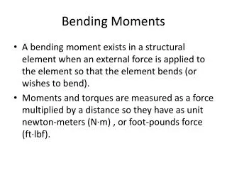
BENDING DEFLECTIONS. 1. Strain definition:. 2. From picture:. 3. Substitution of 2 into 1. 4. Linear strain. M y. M y. 5. Plan e cross-section hypothesis. Geometry of deformation. z. . w. z. x. . 1. Normal strain:. 2. From Hooke law:. 3. Normal stress:.

E N D
1. Strain definition: 2. From picture: 3. Substitution of 2 into 1 4. Linear strain My My 5. Plane cross-section hypothesis Geometry of deformation z w z x
1. Normal strain: 2. From Hooke law: 3. Normal stress: 4. From comparison of 2 and 3: 5. Beam curvature Normal stresses and beam curvature
1. Curavture-bending moment relationship: 2. Formula for curvature of a curve: Differential equation for beam deflection 3. Differential equation for beam deflection w(x)
w(x) w(x) x x w(x) x x w(x) Sign convention The signs of w(x), w’(x) i w’’(x)depend upon co-ordinate system: w>0, w’<0, w’’>0 w>0, w’>0, w’’>0 w>0, w’>0, w’’>0 w<0, w’<0, w’’<0
M>0 M<0 M<0 M>0 Sign convention The sign of M(x) follows adopted convention (M is positive when „undersides” are under tension):
w(x) My x w(x) My Sign convention Combination of the previous two conventions will result in following form of the bending deflection equation: PROVIDED that the positive direction of w axis will coincide with positive direction of bending moment axis pointing towards „undersides”: or x In the opposite case of the two directions discordance the minus sign in the bending equation has to be replaced by the positive sign The direction of x-axis only does not change the sign in the equation of deflection. However, one has to remember that in this case the first derivative of deflectionw’ will change the sign!
x w(x) Integration of the deflection equation To find beam deflection one has to integrate the deflection equation twice. The first integration yields a tangent to the beam axis and, therefore, rotation of the beam cross-section w The next integration results in finding beam deflection: To determine the values of integration constants C and D we need to formulate boundary conditions
w=0 w=0 w=0 w=0 w=0 w=0 A B w=0 w’=0 w=0 w’=0 w=0 w’=0 Integration of the deflection equation The boundary conditions have to represent supports of beam: NOTICE: As we do not take into account normal forces all three cases shown in the row A or B are equivalent with respect to deflections calculation.
Integration of the deflection equation In a general case when moment bending equation cannot be given by in the analytical form for the whole beam it has to be formulated and integrated for all characteristic sections of a beam As a consequence we need to find 2n constants of integration (where n denotes number of characteristic sections) and to write down 2n-2 (2 boundary conditions correspond to beam supports) additional adjustment conditions at the neighbouring characteristic sections This procedure yields the set of 2n linear algebraic equations. The solution of this set can be cumbersome and it is advisable only if need an analytical form of a bending deflection for the whole beam.
n 1 6 2 4 3 5 Example of the boundary conditions adjustment w1=w2 w2=w3 w3=w4 w4=w5 w5=w6 w6=0 w1=0 w’2=w’3 w’3=w’4 w’5=w’6 w’6=0 w’1=w’2 Independent integration Adjustment of first derivatives Adjustment of the deflections
? ? Mohr method STATICS DEFLECTIONS This equation (7) is „integrated” on the basis of M(x)iQ(x) definitions when external loading q(x)and boundary conditions are known . Why not to use the same method to determine the deflections?
STATICS - Fictitious domain DEFLECTIONS - Real domain I F CF= CR , DF=DR wR(x)MF(x) , w’R QF(x) T H E N
Fundamental requirement to be satisfied is that fictitious and real beams have the same length (0 ≤ xR ≤ l, 0 ≤ xF ≤ l). From the condition: [1/m] follows, that the only loading of the fictitious beams will be continuous loading of the dimension [Nm/(Nm-2m4)]=[ m-1] distributed exactly like bending moment distribution for the real beam. Therefore, the bending moment and shear force distributions in the fictitious beams cannot contain any discontinuities (no loading in form of concentrated moments or forces exists). CF= CR , DF=DR To satisfy the conditions: the kinematical conditions have to bet set upon the fictitious beam in such a way that in characteristic points will be: wR(x)MF(x) , w’R QF(x) So, if for the real beam wR=0 in a givenpoint, then for the fictitious beam has to be MF=0 in this point.Similarly ifw’R=0then QF =0 etc.
Example #1 Example #2 Supports (KBC)R Real beam Deflection wR Rotation w’R Bending moment MF Shear forceQF Fictitious beam Supports (KBC)F
Example #3 Example #4 Supports (KBC)R Real beam Deflection wR Rotation w’R Bending moment MF Shear forceQF Fictitious beam Supports (KBC)F
Real beam BELKA FIKCYJNA Built-in support Hinge Pin-pointed support Free end Fictitious beam
Real beam w Bending moment for the fictitious beam Fictitious beam loading Fictitious beam Bending moment diagram for fictitious beam Elementary but troublesome ! ≡ deflections of the real beam
Mohr method applied to the evaluation of deflections and rotations in chosen points P EJ x B A a w l Pa a/3 2a/3 l-a/3 (Pa/EJ)(a/2) Straight line w 3rd order parabola wA= Pa3/3EJ w’A= Pa2/2EJ wB= [Pa2/2EJ][l-a/3] w’B= Pa2/2EJ Bending moments for the fictitious beam MAF=wA= (Pa/EJ)(a/2)(2a/3)= Pa3/3EJ Pa/EJ [Pa2/2EJ][l-a/3] MBF=wB= (Pa/EJ)(a/2)[l-a/3]= Shear forces for the fictitious beam: QAF=QBF=w’A=w’B= (Pa/EJ)(1/2)a= Pa2/2EJ
P P A a a = l Pl/EJ l/3 2l/3 Pl/EJ)(1/2)l Special case: a=l EJ x B wB= Pl3/3EJ = wmax w’B= Pl2/2EJ w Bending moment for the fictitious beam Pl Pl3/3EJ MBF=wB= Pl/EJ)(1/2)l[2l/3]= Shear forces for the fictitious beam QAF=QBF=w’A=w’B= Pl/EJ)(1/2)l= Pl2/2EJ
P EJ x B A a w l wmax wmax w Special example: end beam deflection as the function of force position 1,0 0,75 0,63 0,5 0,31 0,25 0,01 0,61 0,25 0,5 0,75 1,0 [Pa2/2EJ][l-a/3] wB=
Area and centre of gravity for parabolic shapes Parabola of nth degree Area: A= ab/(n+1) Horizontal tangent a Position of the centre of gravity: c= b/(n+2) c b n A c 0 1 2 3 … ab ab/2 ab/3 ab/4 … b/2 b/3 b/4 b/5 …
Let us differentiate twice the equation: making use of M-Q-q relationships Second differentiation: General bending equation First differentiation yields: Double integration of the equation w”= - M/EJ allows for finding rotations and deflections:
DIFFERENTIATION I N T E G R A T I O N General bending equation The overall picture of bending problem Loading Shear force Bending moment; Curvature Deflection Rotation
If EJ changes along beam axis EJ(x), then differential equationfor displacement becomes: Therefore the points in which bending stiffness changes are also a characteristic point.
Deflection of a beam of variable stifness EJ2 > EJ1 P EJ P x a2 a1 K K w w l Pl3/3EJ wK= Pl Pl Pl/EJ EJ2 a1 x l Pl/EJ2 {Pl/EJ2} {1-J2/J1} Pa2/EJ2 Pl/EJ1 {Pa2/EJ2} {1-J2/J1} Pa2/EJ1 {Pa2} {1-J2/J1} OR… Pl/EJ2 EJ2 {P(l-a2)/a1} {1-J2/J1} wK= ? {Pl/EJ2} {1-J2/J1}
EJ2 > EJ1 P EJ P x a2 a1 K K w w l Pl3/3EJ wK= Pl Pl Pl/EJ EJ2 a1 x l Pl/EJ2 {Pl/EJ2} {1-J2/J1} Pa2/EJ2 Pl/EJ1 {Pa2/EJ2} {1-J2/J1} Pa2/EJ1 {Pa2} {1-J2/J1} OR… Pl/EJ2 EJ2 {P(l-a2)/a1} {1-J2/J1} {Pl/EJ2} {1-J2/J1}