Download
1 / 39
410 likes | 665 Views
Surge Protective Devices. Chris Martin Sales Manager Surge Protection Devices. 80% - Internal Disturbances Load switching Variable frequency drives Lighting and air handlers 20% - External Disturbances Utility load switching Smart grid Lighting strikes Cloud to cloud

E N D
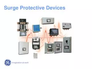
Surge Protective Devices Chris Martin Sales Manager Surge Protection Devices
80% - Internal Disturbances Load switching Variable frequency drives Lighting and air handlers 20% - External Disturbances Utility load switching Smart grid Lighting strikes Cloud to cloud Cloud to ground Cloud to man-made object Where surges originate
Cause disruptions in computer signals and processors Degrade component junctions causing “random” delayed failure Cause instant damage to electrical components Surge damage
How SPDs work Cross Section of a MOV 20,000v Eliminated Voltage • Clamped Voltage(depends on surge level) • Turn on Voltage(always the same) 1,500v Clamped Voltage SPD 150v Turn on Voltage Load Source
UL 1449 2nd Edition 2005 2nd Edition 2005 Revision (effective 2/9/2007) Expanded OVERVOLTAGE Testing (2 x nominal voltage) Added 7 hour intermediate fault current levels 10 amps 100 amps 500 amps 1000 amps SPD manufacturers pass this new requirement by either adding fusing per MOV, thermal sensing technology, or requiring an external OCPD for the safe removal of the SPD
20 microseconds 5000 microseconds 20 mm MOV Surge Current Rating Curve 10000 1 2 10 1000 10 2 10 3 10 4 100 10 5 Surge Current 10 6 Indef. 10 Impulse Duration (Microseconds) 1 10 100 1000 10000 At 20 micro-seconds the MOV can protect up to 6500Amps (1 time) at 5000 micro-seconds that same MOV can only protect up to 30Amps
UL 1449 3rd Edition Creates SPD types (Type1, Type2, Type3, Type4) Surge Arrestor, Lightning Arrestor, TVSS New Nominal Discharge Surge Current test, In Thermal “stress” test Tested MCOV per mode. No longer a claimed value SVR 6kV, 500A replaced with VPR 6kV, 3kA Surge Arrestor incorporated into UL1449 as Type 1 device
SPD Types - UL 1449 3rd Ed. Type 1 SPD (LINE SIDE) Permanently Connected SPD – Installation between the secondary of the service transformer and the LINE side of the service disconnect over current device, as well as the LOAD side, including watt-hour meter socket enclosures. (Not exceeding 1000V) Competitors Surge Arrestor Needs a breaker to pass UL testing Secondary Surge Arrestor
SPD Types (Continued) Type 2 SPD (LOAD SIDE) Permanently Connected SPD intended for installation on the LOAD side of the service disconnect over current device, including SPDs located at the branch panel.
SPD Types (Continued) Type 3 SPD Point of utilization SPDs, installed a minimum of 10 meters (30 feet) from the electrical service panel, for example cord connected, direct plug-in (DPI), receptacle type and SPDs installed at the utilization equipment being protected.
SPD Types (Continued) Type 4 SPD Component SPDs, including discrete components as well as component assemblies. (Note: as proposed the 3rd Edition will allow Type 4 SPDs to be tested and applied where Types 1 and 2 are allowed)
Measured Limiting Voltage (MLV) All SPD Types are to be tested to 6kV/3kA - 3 pulses per mode with applied voltage. VPR is determined by averaging results. (Per 34.9 and Table 34.1) SVR 6kV/500A Good reading 400v or 500v VPR 6kV/3kA Good reading 700v, 800v, 900v, or as high as 1000v Higher surge current results in higher clamping voltages
Type 1: Choose 10kA or 20kA/Mode Type 2: Choose 3kA, 5kA, 10kA, or 20kA Surge unit at chosen surge value Apply chosen over voltage to unit within 1s for 1min Nominal Discharge Current Test (In)
2008 NEC COPS - Critical Operations Power Systems NEC guideline to increase protection and reliability of the power infrastructure for critical facilities What are Critical Facilities? Government agency (Federal, state, municipal) Facility engineering Facilities that if destroyed may disrupt: National security, the economy, public health, or safety To include HVAC, fire alarm, security, communications, and signaling
2008 NEC NEC Section 708.20 (D) Surge Protective Devices must be used to comply SPDs must be used for each voltage at the facility Service Entrance Distribution panels
Improving SPD Installed Performance How does lead length affect the installed performance of a surge protective device? Does an internally mounted SPD outperform an externally mounted SPD? Impact of upstream OCPDs
How are SPDs Tested? • 6 inches outside of the enclosure The surge is injected here Clamping characteristics are recorded by an Oscilloscope • Phase length + Neutral length affect the performance of the SPD
The surge must travel through the phase through the SPDand through Neutral Internally Mounted Lead Length Phase length + Neutral length= SPD clamping voltage
Lead Length Lead length affects the installed performance of a SPD 10’ sections of cable (commonly used sizes) 14 AWG 10 AWG 6 AWG Apply IEEE defined 20kV/10kA surge Measure the voltage drop
Wire size Voltage drop across 10 foot cable when exposed to a 20kV/10kA surge 14 AWG 2,650v 10 AWG 2,400v 6 AWG 2,350v What does this do to the installed performance of the SPD?
HPI Voltage Drop Voltage drop across 10 foot cable when exposed to a 20kV/10kA surge 10 AWG 560v 6 AWG 560v
Lead Length Impact 83% improvement
Breaker Impact Does a breaker upstream of an SPD limit the effectiveness of the SPD? Breakers have surge trip and surge failure values: The SCCR value is based on 60Hz current, not surge current! Type 2 SPDs must be installed behind a breaker! These values are based on testing performed by Current Technology’s Surge generator on commercially available off the shelf breakers.
ISM Design • Utilizes TPMOV technology • Bus Bar construction • N-G filter (removable) • Improved L-N Filter • 100% surge rated • Reduced weight • Individually monitored MOVs • Advanced monitoring 300kA Model
The TPMOV DRC contacts DRC switch 50mm MOV Thermal spring Barrier Barrier spring
Select3 (SL3) Listed by UL to UL1449 3rd Edition as a Type 1 SPD 50kA, 100kA, 150kA, 200kA, 250kA, 300kA per mode TPMOV/Selenium Hybrid Option for enhanced selenium Test reports for single and repetitive surge testing Surge rated disconnect with line side barrier DTS-2 internal test port option 6 levels of monitoring 20 year warranty THE SERVICE ENTRANCE SURGE PROTECTOR OF CHOICE
TransGuard3 (TG3) • Listed by UL to UL1449 3rd Edition as a Type 1 SPD • 50kA, 100kA, 150kA, 200kA, 250kA, 300kA per mode • TPMOV Technology • RoHS compliant • Test reports for single and repetitive surge testing • Surge rated disconnect with line side barrier • DTS-2 internal test port option • 6 levels of monitoring • 15 year warranty
Panel Extension (PX3) • Listed by UL to UL1449 3rd Edition as a Type 1 SPD • 50kA, 100kA, 150kA, 200kA per mode • 9 inch height for 50kA-100kA units • TPMOV Technology • RoHS compliant • Test reports for single and repetitive surge testing • DTS-2 internal test port option • 6 levels of monitoring • 15 year warranty
DTS-2 Tester The ONLY proactive test kit for SPDs on the market Updated test card for both MOV and TPMOV based products with or without selenium Validates “health” of surge components Compares installed clamping performance to original factory values Detects and provides early warning for stressed components Can be used to evaluation competitive products performance Part of any startup or commissioning Validates integrity of upstream Xo bond
M1 Standard Monitoring • LED indication per phase • Audible alarm • Alarm silence switch • 2 sets of dry relay contacts • Tri-colored LED that reports on % protection • Green = 75% or greater • Orange = 75% - 40% • Red = 40% or less • Extinguished = Loss of protection
M2 Monitoring Option All M1 monitoring options Surge counter
M3 Option New Mastermind Includes all M1 monitoring features Time/Date stamp Duration and Magnitude User settable thresholds Tracks Sags, swells surges, dropouts, outages, THD, frequency, Volts RMS, % protection Local character display ModBus remote communications M4E Option • New Mastermind • Includes all M1 monitoring features • Time/Date stamp • Duration and Magnitude • User settable thresholds • Tracks • Sags, swells surges, dropouts, outages, THD, frequency, Volts RMS, % protection • Local character display • ModBus and Ethernet remote communications • Web based interface
M5 Option Adds Large Graphics Display Includes all M1 monitoring features Time/Date stamp Duration and Magnitude User settable thresholds Tracks Sags, swells surges, dropouts, outages, THD, frequency, Volts RMS, % protection Local character display ModBus remote communications M6E Option • Adds Large Graphics Display • Includes all M1 monitoring features • Time/Date stamp • Duration and Magnitude • User settable thresholds • Tracks • Sags, swells surges, dropouts, outages, THD, frequency, Volts RMS, % protection • Local character display • ModBus and Ethernet remote communications • Web based interface
Review Specs need to be Updated to include new requirements outlined in UL1449 3rd Edition Externally mounted SPDs offer a safer installed alternative without affecting performance External OCPDs can have an affect on the installed performance of the SPD Ask for documentation. Single surge, repetitive surge, and tested MCOV value Questions?