Download
1 / 58
610 likes | 775 Views
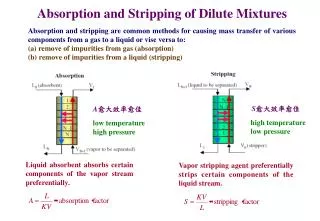
Packed absorption and stripping columns. WHAT IS GAS ABSORPTION????. Absorption, or gas absorption, is a unit operation used in the chemical industry to separate gases by washing or scrubbing a gas mixture with a suitable liquid .

E N D
WHAT IS GAS ABSORPTION???? • Absorption, or gas absorption, is a unit operation used in the chemical industry to separate gases by washing or scrubbing a gas mixture with a suitable liquid . • The fundamental physical principles underlying the process of gas absorption are the solubility of the absorbed gas and the rate of mass transfer. One or more of the constituents of the gas mixture dissolves or is absorbed in the liquid and can thus be removed from the mixture. In some systems, this gaseous constituent forms a physical solution with the liquid or the solvent, and in other cases , it reacts with the liquid chemically.
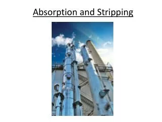
The purpose of such scrubbing operations may be any of the following : Gas purification (eg , removal of air pollutants from exhausts gases or contaminants from gases that will be further processed) , Product Recovery , or production of solutions of gases for various purposes. • The absorber may be a packed column , plate column , spray column , venturi scrubbers , bubble column , falling films , wet scrubbers ,stirred tanks
Gas absorption is usually carried out in vertical counter current columns. The solvent is fed at the top of the absorber , whereas the gas mixture enters from the bottom .The absorbed substence is washed out by the solvent and leaves the absorber at the bottom as a liquid solution . The solvent is often recovered in a subsequent stripping or desorption operation . This second step is essentially the reverse of absorption and involves counter current contacting of the liquid loaded with solute using and inert gas or water vapor .
COUNTERCURRENT FLOW • Countercurrent tower which may be either a packed or spray tower, filled with bubble cape trays or of any internal construction to bring about liquid gas contact. • Mole ratio may be define as • Y = y/(1-y) • X = x/(1-x) • Here y for gas stream and x for liquid stream.
Material balance Gs = G(1-y) = G/(1+Y) Ls = L(1-x) = L/(1+X) NOW Gs(Y1 - Y) = Ls(Xs - X) AND Gs(y1/(1-y1) – y/(1-y)) = Gs(p1/(1-p1) – p/(1-p)) = Gs(x1/(1-x1) – x/(1-yx))
MINIMUM LIQUID-GAS RATIO • In the design of absorbers, the quantity of gas to be treated G or Gs, the terminal concentrations Y1 and Y2,and the composition of the entering liquid X2 are ordinarily fixed by process requirements. • The operating line must be pass through point D and must end at the ordinate Y. • Liquid gas ratio is define by L/G • Graph of minimum liquid-gas ratio can be shown as behind slide.
CO-CURRENT FLOW • When gas and liquid flow cocurrently, the operating line has a negative slope. -L/G • There is no limit of this ratio, but an infinitely tall tower would produce an exit liquid and gas in equilibrium • In cocurrentfowrequirred height of tower should be higher then in counter current flow.
Counter-current multi-stage absorption (Tray absorber): • In tray absorption tower, multi-stage contact between gas and liquid takes place. • In each tray, the liquid is brought into intimate contact of gas and equilibrium is reached thus making an ideal stage. • In ideal stage, average composition of liquid leaving the tray is in equilibrium with liquid leaving that tray. • The most important step in design of tray absorber is the determination of number of trays. • The schematic of tray tower is presented in figure. • The liquid enters from top of the column whereas gas is added from the bottom.
In tray absorption tower, multi-stage contact between gas and liquid takes place. In each tray, the liquid is brought into intimate contact of gas and equilibrium is reached thus making an ideal stage. In ideal stage, average composition of liquid leaving the tray is in equilibrium with liquid leaving that tray. The most important step in design of tray absorber is the determination of number of trays. The liquid enters from top of the column whereas gas is added from the bottom. The efficiency of the stages can be calculated as:
The following parameters should be known for the determination of “number of stages”: (1) Gas feed rate (2) Concentration of gas at inlet and outlet of the tower (3) Minimum liquid rate; actual liquid rate is 1.2 to 2 times the minimum liquid rate. (4) Equilibrium data for construction of equilibrium curve • Now, the number of theoretic stages can be obtained graphically:
(A) Graphical Method for the Determination of Number of Ideal Stages: • Overall material balance on tray tower: Gs(YN+1 -Y1) = Ls(XN -X0) This is the operating line for tray tower • If the stage (plate) is ideal, (Xn, Yn) must lie on the equilibrium line, Y*=f(X). • Top plate is located at P(X0, Y1) and bottom plate is marked as Q(XN, YN+1) in X-Y plane. • A vertical line is drawn from Q point to D point in equilibrium line at (XN, YN). • From point D in equilibrium line, a horizontal line is extended up to operating line at E (XN-1, YN).
The region QDE stands for N-th plate. We may get fraction of plates. • In that situation, the next whole number will be the actual number of ideal plates. • If the overall stage efficiency is known, the number of real plates can be obtained from Equation A.
Example: It is desired to absorb 95% of acetone by water from a mixture of acetone and nitrogen containing 1.5% of the component in a countercurrent tray tower. Total gas input is 30 kmol/hr and water enters the tower at a rate of 90 kmol/hr. The tower operates at 27ºC and 1 atm. The equilibrium relation is Y=2.53X. Determine the number of ideal stages necessary for the separation using graphical method.
Solution: • Basis: 1 hour • G(N+1)=30 kmol • Y(N+1)=0.015 • Lo=90 kmol • Moles acetone in = 30×0.015 moles=0.45 moles • Moles nitrogen in = (30-0.45) moles=29.55 moles • Moles acetone leaving (95% absorbed) = 0.45×(1-0.95) moles=0.0225 moles • Gs=29.55 moles • Ls=90 moles • α=2.53 [as, Y=2.53X]
𝑌1 = 0.0225/29.55 = 7.61 × 10^−4 • 𝑌(𝑁+1)= 0.015 • Equation.. 𝐺𝑠𝑌(𝑁+1)− 𝑌1= 𝐿𝑠(𝑋𝑁− 𝑋0) 29.55 × 0.015 − 7.61 × 10^−4= 90(𝑋𝑁− 0) • XN=4.68×10^-3 • Solution by graphical method,Construction of operating line PQ: P(X0,Y1)=P(0, 7.61×10^-4) Q(XN, YN+1)=Q(4.68×10^-3, 0.015) Construction of equilibrium line (Y=2.53X): X 0 0.001 0.002 0.003 0.004 0.005 Y 0 0.00253 0.00506 0.00759 0.01012 0.01265 From graphical construction in Figure , the number of triangles obtained is more than 7. Hence number of ideal stages is 8.
Rate of absorption • Volumetric mass transfer coefficients (Kya, etc.) are used for most calculations, because it is more difficult to determine the coefficients per unit area and because the purpose of the design calculation is generally to determine the total absorber volume. • Kya=overall volumetric mass-transfer coefficient, kmol/(m3·h·unit mole fraction). • a=effective area of interface per unit packed volume, m2/m3
Simplicity Treatment • The following treatment applies to lean gases(up to 10% solute): • (a) Correction factorsfor one-way diffusion are omitted for simplicity. • (b) Changes in gas and liquid flow rates (V and L) are neglected. • (c) kxa, kya, Kya, Kxa can be considered as constants.
the rate of mass transfer: • r=NA [kgmol/(m2·h·unit mole fraction)]
Let r =rate of absorption per unit volume, kgmol/(m3·h) • It is hard to measure or to predict a, but in most cases it is not necessary to know its actual value since design calculations can be based on the volumetric coefficients.
Determining the interface composition (yi, xi) • (yi, xi) is also hard to measure, but it can be obtained from the operating-line diagram • Thus a line drawn from the operating line with a slope –kxa/kya will intersect the equilibrium line at (yi, xi).
Determining the overall coefficients: Using the local slope of the equilibrium curve m, we have Therefore, Similarly,
=overall resistance to mass transfer = resistance to mass transfer in the gas film =resistance to mass transfer in the liquid film
When • Or, When the coefficients kya and kxa are of the same order of magnitude, and m is very much greater than 1.0, the liquid film resistance is said to be controlling. That is, • Gas film “controls” and Liquid film “controls”
Liquid film controlling means that any change in kxa has a nearly proportional effect on both Kxa and Kya and on therate of absorption, whereas a change in kya has little effect. • Examples of Liquid film controls: Absorption of CO2, H2,O2,Cl2 in water; • When the solubility of the gas is very high, m is very small and the gas-film resistance controls the rate of absorption. • Examples of gas-film controls: Absorption of HCl, NH3 in water; NH3 in acid solution; SO2, H2S in basic solvent.
With gases of intermediate solubility both resistances are important, but the term controlling resistance is sometimes used for the larger resistance. • The absorption of NH3 in water is often cited as an example of gas-film control, since the gas film has about 80 to 90 percent of the total resistance.
S=cross sectional area; • SdZ=differential volume in height dZ. • The amount absorbed in section dZ is Vdy. • Fig. Diagram of packed absorption tower
The equation for column height can be written as follows: =overall number of transfer units [NTU], based on gas phase. =overall height of a transfer unit [HTU], based on gas phase. • Number of transfer units
(1)If the operating line and equilibrium line are straight and parallel,
If the operating line and equilibrium line are straight and parallel, NTP=Number of theoretical plates • (2) For straight operating and equilibrium line (not parallel), Similarly,
NTP=Number of theoretical plates • (3) When the operating line is straight but steeper than the equilibrium line,
Similarly, for straight operating and equilibrium line (not parallel),
The overall height of a transfer unit [Hoy OR Hox] can be defined as the height of a packed section required to accomplish a change in concentration equal to the average driving force in that section. • Common equations for calculations of height of packed section: • height of packed section=height of a transfer unit number of transfer units • There are four kinds of transfer units:
Gas film: Liquid film: Overall gas: Overall liquid: • Four kinds of transfer units:
Alternate forms of transfer coefficients • The gas-film coefficients reported in the literature are often based on a partial –pressure driving force instead of a mole-fraction difference and are written askga or Kga. • Similarly liquid-film coefficients may be given as kLa or KLa, where the driving force is a volumetric concentration difference. [kL=kc defined by Eq.(17.36)]
Let Where, =molal mass velocity, kgmol/m2 h =mass velocity of gas stream based on total tower cross section, kg/m2 h =mass velocity of liquid stream based on total tower cross section, kg/m2 h
The terms HG, HL, NG AND NL often appear in the literature instead of Hy, Hx, Ny AND Nx, as well as the corresponding terms for overall values, but here the different subscripts do not signify any difference in either units or magnitude. • Relationships among different kinds of height of a transfer unit:
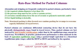
1. HETP - approach Packed columns are continuous contacting devices that do not have the physically distinguishable stages found in trayed columns. In practice, packed columns are often analyzed on the basis of equivalent equilibrium stages using a Height Equivalent to a Theoretical Plate (HETP): Knowing the value of the HETP and the theoretical number of stages n of a trayed column, we can easily calculate the height H of the column : The HETP concept, unfortunately, has no theoretical basis. HETP values can only be calculated using experimental data from laboratory or commercial-size columns.
y2< y spec G, y2 L, x2 T, p G, y1 L, x1 2. Absorption: Mass transfer approach (HTU, NTU) For packed columns, it is preferable to determine packed height from a more theoretically based method using mass transfer coefficients. The absorption problem is usually presented as follows. There is a polluted gas stream coming out from a process. The pollutant must be recovered in order to clean the gas. z = H At the bottom and the top of the column, the compositions of the entering and leaving streams are: y x Furthermore, we introduce the coordinate z, which describes the height of the column. z = 0 Process The green, upper envelope is needed for the operating line of the absorption column.
First, we need a material balance around the green, upper envelope of the column. It is the operating line, going through the point (x2,y2): y y1 y* = m x Then we need the equilibrium condition: y2 x2 x1 x We can now draw the equilibrium and operating line into the diagram. From the operating line with the smallest slope (Lmin/G), we can get (L/G) with the known formula:
As a third equation, we need a mass transfer rate equation. We take a small slice of the column. The material balance over the “gas side” of this slice gives: L G N L G S is the cross-sectional area of the tower. Please note that N, G and L are defined as fluxes and not as molar flow rates [mol/s]: Determination of the packed height of a column most commonly involves the overall gas-phase coefficientKy because the liquid usually has a strong affinity for the solute. Its driving force is the mole fraction difference (y-y*):
Dividing the mass transfer rate equation by S and z, we get: Because we want a differential height of the slice, we let z 0. Introducing the definition of N: Separating variables and integration gives: Taking constant terms out of the integral and changing the integration limits: HOG NOG The right-hand side can be written as the product of the two terms HOG and NOG: