Download
1 / 50
510 likes | 658 Views
Outline Resistances in Series and Parallel Network Analysis by Using Series and Parallel Equivalents Voltage-divider and Current-Divider Circuits Node-Voltage Analysis Mesh-Current Analysis Thevenin and Norton Equivalent Circuits.

E N D
Outline • Resistances in Series and Parallel • Network Analysis by Using Series and Parallel Equivalents • Voltage-divider and Current-Divider Circuits • Node-Voltage Analysis • Mesh-Current Analysis • Thevenin and Norton Equivalent Circuits
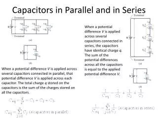
In a parallel ckt, the voltage across each element is the same. Applying Ohm’s law, we can write
Voltage Division When a voltage is applied to a series combination of resistances, a fraction of a voltage appears across each of the resistances.
Current Division The total current flowing into a parallel combination of resistances divides, and a fraction of the total current flows through each resistance.
Although they are very important concepts, series/parallel equivalents and the current/voltage division principles are not sufficient to solve all ckt problems. That’s how the node-voltage analysis comes in.
A node is a point at which two or more ckt elements are joined together. In node-voltage analysis, we first select one of the nodes as the reference node. In principle, any node can be picked to be the reference node. Next, we label the voltages at each of the other nodes. Write equations to solve for the voltages, then the current.
Writing KCL equations in terms of the node voltage: to find the current flowing out of node n through a resistance toward node k, we subtract the voltage at node k from the voltage at node n and divide the difference by the resistance. For example, If vn and vk are the node voltages and R is the resistance connected between the nodes, the current flowing from node n toward node k is given by Note: the positive reference is at the head of the arrow.
Apply KCL at node 2, we get Apply KCL at node 3, we get
Thevenin and Norton Equivalent ckts In this section, we learn how to replace two-terminal ckts Containing resistances and sources by simple equivalent ckts.
Thevenin Equivalent circuits One type of equivalent ckts is the Thevenin equivalent, which Consists of an independent voltage source in series with a resistance.
Thevenizing Procedure • Calculate the open-ckt voltage (Vth) • across the network terminals. • 2. Redraw the network with each • independent source replaced by its internal resistance. This is called “deactivation of the sources”. 3. Calculate the resistance (RTH ) of the redrawn network as seen from the output terminals.
Different methods of finding RTH • For independent sources: Deactivate the sources, i.e. for • independent current source, deactivate it by open circuiting its • terminals and for voltage source, deactivate it by shorting it. To • In case of non-ideal sources, the internal resistance will remain • Connected across the deactivated source terminals. • (b) For dependent sources in addition or in absence of independent • source. • Find open circuit voltage Voc across the open circuited load • terminals. Next short circuit the load terminals and find the short • ckt current (Isc) through the shorted terminals. • The Thevenin’s equivalent resistance is then obtained as • RTh = Voc/Isc
Norton’s Theorem According to this theorem, any two-terminal active network, containing voltage sources and resistance when viewed from its output terminals is equivalent to a constant current source and an internal (parallel) resistance. The constant current source (known as Norton’s equivalent current source) is of the magnitude of the short circuit current at the terminals.
Nortonizing Procedure • Remove RL, and short circuit the terminals a and b. The • current through the short circuited path is Isc or In. • 2. Finding internal resistance of the network by deactivating • all the sources and replace them by its internal resistance. Then • Calculate RN of the redrawn network as seen from the output • Terminals. • 3. Draw the Norton’s equivalent ckt.
Source Transformation A voltage source in series with a resistance is externally Equivalent to a current source in parallel with the resistance, Provided that In = Vt/Rt
Maximum Power Transfer Suppose that we have a two-terminal ckt and we want to connect a Load resistance RL such that the maximum possible power is Delivered to the load. To analyze this problem, we replace the original ckt by its Thevenin Equivalent as shown
Thus, the load resistance that absorbs the maximum power from a Two-terminal ckt is equal to the Thevenin resistance. The maximum power is given by