Download
1 / 62
670 likes | 982 Views
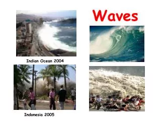
EM Waves/Optics. AP Physics B Chapter 22-23 Notes. Quick Review of Waves. A wave is a traveling disturbance Waves carry energy from place to place. Quick Review of Waves. A longitudinal (compression) wave causes disturbance along parallel to) the direction that the wave propagates.

E N D
EM Waves/Optics AP Physics B Chapter 22-23 Notes
Quick Review of Waves • A wave is a traveling disturbance • Waves carry energy from place to place
Quick Review of Waves A longitudinal (compression) wave causes disturbance along parallel to) the direction that the wave propagates
Quick Review of Waves A transverse wave causes disturbance perpendicular to the direction that the wave propagates
Quick Review of Waves Periodic waves consist of cycles that are reproduced over and over by the source--SHM
Quick Review of Waves A fully cycle is shaded below—the wavelength is the length of one cycle Amplitude is the maximum displacement from the undisturbed position Period is the time taken to complete one cycle. Frequency is the number of cycles per second
Quick Review of Waves Wave propagation velocity depends on wavelength and period distance over time. v = λ/T v = λf
Electromagnetic Waves Maxwell’s equations are key to describing all electric and magnetic phenomena Beyond the scope of this class, but a key hypothesis of Maxwell is a changing Ewill produce B
Producing Electromagnetic Waves Two straight wires connected to an ac generator can create an EM wave Electric part of the wave: The red arrow represents E produced at point P by oscillating charges on the antenna. The black arrows are the E produced by earlier oscillations. The portion of the wave going right is shown.
Producing Electromagnetic Waves Magnetic portion of wave: The current used to create E causes a magnetic field. Using RHR we can determine B is perpendicular to E since E is parallel to I
Producing Electromagnetic Waves Far from the source, the wave propagates itself by the changing E-field producing a B-field and the changing B-field producing an E-field. E&M wave is transverse and can travel in a vacuum since it is a field wave
Electromagnetic Waves Maxwell was able to calculate the speed of EM radiation and determine that is was the same for all types of EM waves and the same in all directions Later this was confirmed experimentally
Electromagnetic Waves Like all waves, EM waves have a frequency and wavelength related by:
Electromagnetic Waves You will be expected to know the relative position of different wave types in the EM spectrum (f and λ)
Speed of Light Michelson was the first to devise an experiment to determine the speed of light
EM Example A station broadcasts AM radio waves whose frequency is 1230 x 103Hz and FM radio waves whose frequency is 91.9 x 10⁶ Hz. Find the wavelength of each type of wave.
Ray Model of Light Wave fronts can be connected by rays that are perpendicular to the wave front (which are curved near the source) Far away from the source wave fronts become (nearly) parallel planes, with rays parallel to each other We will consider light waves as planes and use rays to represent them
Law of Reflection The angle of incidence is equal to the angle of reflection, as measured between the light ray and the normal to the surface. Θi=Θr
Diffuse and Specular Reflection Incident light on rough surfaces is reflected in many directions (draws normals to confirm) Incident light on optically smooth surfaces are reflected parallel to each other Paper, wood, rough water Mirror, calm water, polished metal
Plane Mirrors Light rays from an object reflect off of a plane mirror and make the object seem to be behind the mirror—this is a virtual object because none of the rays actually go through the image
Plane Mirrors Plane Mirror Image Properties • It is upright • It is the same size as the object • It is as far behind the mirror as the object is in front of it (virtual) • It is reversed left to right (to the observer)
Plane Mirrors--Example What is the minimum height mirror needed for a person to see her full reflection?
Spherical Mirrors If the inside surface of the spherical mirror is polished, it is a concave mirror. If the outside surface is polished, is it a convex mirror. R is the radius of curvature of the mirror. The principal axis of the mirror is a straight line drawn through the center of curvature C and the midpoint of the mirror.
Spherical Mirrors The law of reflection still applies—you just have to be careful to draw the normal correctly. Rays coming from a distant object are effectively parallel
Spherical Mirrors Light rays near and parallel to the principal axis are reflected from the concave mirror and converge at the focal point F. The focal length f is the distance between the focal point and the mirror.
Spherical Mirrors Rays that are near the principal axis all converge at F, but rays far from the PA do not This is referred to as spherical aberration and can cause a blurred image
Spherical Mirrors This can be corrected by using a mirror that is small in height compared to its radius of curvature…or using a parabolic reflector…very expensive and hard to make
Spherical Mirrors The last bit of helpful information is the relationship between radius of curvature, r and focal length, f This can be proved by considering similar triangles CAB and FAB f r
Spherical Mirrors To find an image of an object placed in front of a mirror, we will ray tracing. There are three possible rays we will use to find the image. All of the rays will start from the same point on the object (diffuse reflection). The intersection of these three rays will give the position and relative size of the image.
Spherical Mirrors Ray one is parallel to the principal axis and is reflected through the focal point Ray two travels through F and is reflected parallel to the principal axis Ray three travels a line along the center of curvature and is reflected back on itself
Spherical Mirrors Ray one: parallel to the principal axis; reflected through the focal point Ray two: through F and is reflected parallel to the principal axis Ray three: through the center of curvature Intersect at image
Concave Mirrors—Possible Scenarios Place object between C and F • Real image (rays pass through image) • Inverted • Magnified
Concave Mirrors—Possible Scenarios Place object beyond C • Real image (rays pass through image—can be projected on a screen) • Inverted • Reduced in size
Concave Mirrors—Possible Scenarios Place object inside F • Virtual image (no rays pass through image) • Upright • Magnified (cosmetic mirror)
Convex Mirrors—One Story For convex mirrors the image is always upright, virtual and reduced in size “Objects are closer than they appear” Ray One: Parallel to PA and back from focal point Ray Two: Toward focal point and out parallel to PA Ray Three: Toward C and back on itself
Mirror Equation and Magnification We need equations to quantitatively analyze images made by mirrors in addition to the qualitative ray tracing diagrams f = focal length do= object distance di= image distance m= magnification
Mirror Equation and MagnificationConsider a Real Image Produced by a Concave Mirror ho/(-hi) = do/di ho/(-hi) = (do-f)/f Magnification Equation Mirror Equation
Mirror Equation Sign Convention f: is + for concave mirrors; - for convex mirrors do: is always + di: is + on the reflective side of mirror (real image); - when behind the mirror (virtual image) m: is + for an upright image; - for an inverted image ho:is always + hi:is + for upright image; - for inverted image
Mirror Equation—Example P. 22, pg. 659 A shaving mirror is designed to magnify your face by a factor of 1.33 when your face is placed 20 cm in front of it. a) What type of mirror is it? b) Describe the type of image it makes of your face. c) Calculate the radius of curvature.
Refraction Light travels through a vacuum at c = 3.00 x 10⁸ m/s Light travels through materials more slowly than in a vacuum Definition of Index of Refraction The index of refraction of a material is the ratio of the speed of light in a vacuum to the speed of light in the material:
Refraction The greater n is the slower light moves in a given medium
Refraction As a result of the difference in speed between two media, a refracted (transmitted) ray will change direction at the boundary (“SFA” or “FST”). The reflected ray behaves as expected.
Refraction This causes some visual misperceptions—ever step into a shallow creek only to sink up to your hip?
Refraction—Snell’s Law Snell’s Law defines the relationship between the angle of incidence and the angle of refraction nisinθi=nrsinθr
Snell’s Law—Sample Problem The eyes of a person standing at the edge of 1.2m deep swimming pool are 1.6m above the surface of the water. Light coming from a silver dollar at the bottom of the pool enters the person’s eyes at 37º below the horizontal. Draw a picture of the light ray, which leaves the dollar and enters the person’s eyes and calculate the horizontal distance from the person to the dollar.
Total Internal Reflection When light passes from slow to fast media (n1>n2), it bends away from the normal. Eventually θr (θ2)becomes 90oand no light is refracted. This is total internal reflection. The critical angle,θc is defined as the angle of incidence that makes the angle of refraction equal 90o. sinθc= n2/n1 n1sinθ1= n2sin θ2 n1sinθc= n2sin90o Total internal reflection
Total Internal Reflection—Applications TIR is useful in the design of optical instruments. For example is glass n =1.5 and air are used, θc = 42o.This can be used to bend light 90o or 180o.
Total Internal Reflection—Applications Another useful application is fiber optics (“light pipes”). Light can travel with little energy loss in any direction using two different glass/plastic materials. Send data at the speed of light!
Lenses Lenses refract light in such a way that an image of the light source is made. Converging lenses focus ray parallel to the PA at the focal point, F. The focal length is f.
Lenses With diverging lenses, rays parallel to the PA appear to originate from the focal point, F. The focal length is f.