Download
1 / 8
80 likes | 164 Views
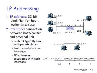
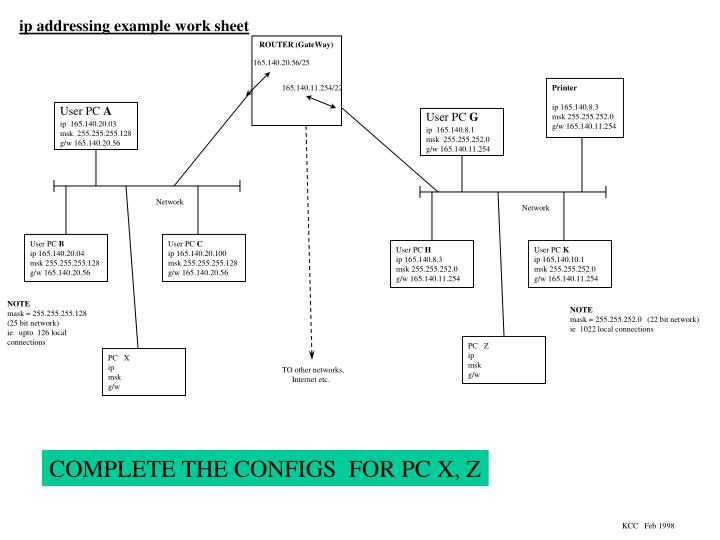
ip addressing example work sheet. ROUTER (GateWay). 165.140.20.56/25. 165.140.11.254/22. Printer ip 165.140.8.3 msk 255.255.252.0 g/w 165.140.11.254. User PC A. User PC G. ip 165.140.20.03 msk 255.255.255.128 g/w 165.140.20.56. ip 165.140.8.1 msk 255.255.252.0

E N D
ip addressing example work sheet ROUTER (GateWay) 165.140.20.56/25 165.140.11.254/22 Printer ip 165.140.8.3 msk 255.255.252.0 g/w 165.140.11.254 User PC A User PC G ip 165.140.20.03 msk 255.255.255.128 g/w 165.140.20.56 ip 165.140.8.1 msk 255.255.252.0 g/w 165.140.11.254 Network Network User PC B ip 165.140.20.04 msk 255.255.255.128 g/w 165.140.20.56 User PC C ip 165.140.20.100 msk 255.255.255.128 g/w 165.140.20.56 User PC H ip 165.140.8.3 msk 255.255.252.0 g/w 165.140.11.254 User PC K ip 165.140.10.1 msk 255.255.252.0 g/w 165.140.11.254 NOTE mask = 255.255.255.128 (25 bit network) ie upto 126 local connections NOTE mask = 255.255.252.0 (22 bit network) ie 1022 local connections PC Z ip msk g/w PC X ip msk g/w TO other networks, Internet etc. COMPLETE THE CONFIGS FOR PC X, Z KCC Feb 1998
Ethernet Reminder P C P C P C P C P C P C BRIDGE P C P C P C P C P C P C the original single segment network. all devices share the same cable or collision domain. Remember Ethernet CSMA/CD = Carrier Sense,Multiple Access, Collision Detection….. only one device can use the cable at one time. with the use of layer2 bridges segments could be connected together. each work group has its own collision domain. traffic is kept local using the mac address. Unfortunately, broadcast traffic is sent to all segments (all users in same broadcast domain). only one device in each segment can use the cable at one time. P C P C P C with the use of a layer 3 router the three segments become separate networks with their own collision domain and broadcast domain. The router can makes decisions based upon protocol, company policy, traffic levels etc… only one device in each segment can use the cable at one time. ROUTER P C P C P C P C P C P C KCC Feb 1998
Ethernet Reminder 2 P C P C P C P C P C P C P C P C P C P C P C S W I T C H H U B the hub or repeater (layer 1) extends the physical specification and enables use of cabling over a greater distance. all devices still are in same collision domain and same broadcast domain. only one device can use the the above network at one time. the use of a simple ethernet switch provides an ethernet bridge for each port. each switched port is a separate collision domain. the switch is a layer 2 device hence all ports are in the same broadcast domain. P C 4 P C 5 P C 6 to/from other routers and switches in the company network ROUTER use of more complex configurations can provide VLANs (virtual local area networks) where PC 1,2,3,7 & 8 are in one vlan and PC 4,5,6 & 9 are in another. each vlan is a separate broadcast domain and each switch port can provide a separate collision domain. S W I T C H interswitch link S W I T C H P C 1 P C 2 P C 3 P C 7 P C 8 P C 9 KCC Feb 1998
FRAME CONSTRUCTION EXAMPLE LAYER 5 FTP HEADER FTP DATA Example FTP session LAYER 4 SEGMENT TCP HEADER TCP DATA Example TCP PORT # 21 = FTP content LAYER 3 PACKET IP HEADER IP DATA Example PROTOCOL #6 = TCP content LAYER 2 FRAME FRAME HEADER DATA Example DIX frame TYPE #0800 = IP content LAYER 1 Preamble DATA SIGNAL KCC August 1999
TCP SEGMENT CONSTRUCTION 0 4 8 16 19 24 31 source port destination port FLAGS; U Urgent A Acknowledgement P Push R Reset S Synchronize SYN F FIN sequence number acknowledgement number offset reserved U A P R S F window checksum urgent pointer TCP = IP protocol # 6 options (variable length) padding LAYER 4 d a t a UDP SEGMENT CONSTRUCTION 0 4 8 16 19 24 31 source port destination port UDP = IP protocol # 17 length UDP checksum LAYER 4 d a t a KCC August 1999
IP PACKET CONSTRUCTION 0 4 8 16 19 24 31 version hdr length TOS total packet length identification flags fragment offset TTL protocol # header checksums source address LAYER 3 destination address options (variable length) padding d a t a LAYER 2 FRAME FRAME HEADER DATA KCC August 1999
ETHERNET FRAME CONSTRUCTION LAYER 2 64 to 1518 Bytes long preamble/SD destination mac address source mac address TYPE/LENGTH 802.2 SSAP/DSAP DATA FCS 41 to 1500 Bytes long 4 8 6 6 2 4 (+5) L E N G T H I N B Y T E S NOTE… Ethernet DIX frame preamble is 8 bytes long with no SD byte, Ethernet DIX frame has TYPE field and no LENGTH or 802.2 fields. Ethernet IEEE 802.3 frames have 7 byte preamble, 1 byte SD, Ethernet IEEE 802.3 frames have LENGTH field and no TYPE field, Ethernet IEEE 802.3 frames have 802.2 field for 2 byte DSAP, 2 byte SSAP, 2 control bytes and 5 byte SNAP (if used DSAP and SSAP = 0xAA). Therefore the largest Ethernet frame size should be1518 bytes and the minimum frame size should be 64 bytes in order to stay within the Ethernet specification and be able to detect a collision. The frame size was extended to 1522 bytes by a IEEE 802.3 committee workgroup (802.3ac) to support VLAN tagging using 802.1Q but several manufactures equipment still will not support giant frames (larger than 1518). Frame sizes have been pushed even further with the latest technologies. ISL (Inter Switch Link) VLAN tagging extends the frame by an additional 30 Bytes, MPLS (Multi Protocol Label Switching) adds 4 Bytes for each label….. etc. etc. so it is not unusual to see giant frames on today’s networks. KCC August 1999
UTP & AUI Ethernet Cabling LAYER 1 pin assignment; pin # MDI-X function MDI function RJ-45 SOCKET VIEW 1 Rx + Tx + 2 Rx - Tx - 3 Tx + Rx + 6 Tx - Rx - 1 2 3 4 5 6 7 8 NOTE; most Ethernet equipment has MDI-X ports (Media Dependant Interface Crossover) and some supply an MDI or switchable MDI/MDI-X to enable connection of to 10BaseT devices without the use of a crossover cable. NOTE: Chiron makes use of RJ-11 connectors for the Cat-3 cabling for example an RJ-11 to RJ-45 cable ; RJ-11 pin # RJ-45 pin # NOTES; 1 5 2 6 3 1 4 2 5 3 6 4 Some equipment uses the 15 pin D AUI connection ; pin # function 1 ground 2 CI-A 3 DO-A 4 ground 5 DI-A 6 VDC ground 9 CI-B 10 DO-B 11 ground 12 DI-B 13 VDC +12 14 ground 15 ground KCC Feb 1998