Download
1 / 28
280 likes | 393 Views
Application Performance Evaluation and Recommendations for the DYNES Instrument . Shawn McKee / Univ. of Michigan Presenting CHEP 2013 in Amsterdam Tuesday, October 15 th 2013. Talk Overview. Introduction to virtual circuits and DYNES Limitations of virtual circuits in practice

E N D
Application Performance Evaluation and Recommendations for the DYNES Instrument Shawn McKee / Univ. of Michigan Presenting CHEP 2013 in Amsterdam Tuesday, October 15th 2013 Shawn McKee / CHEP2013
Talk Overview Introduction to virtual circuits and DYNES Limitations of virtual circuits in practice Exploration of solutions Summary and Conclusion Shawn McKee / CHEP2013
Networking and Virtual Circuits • For users, networks are typically black boxes that try to transport bits between the source and destination in a “best effort” way. • Traffic is not differentiated; all flows are handled in the same way. Simple and powerful but problematic for some use-cases: • Latency sensitive applications: remote control, video conferencing, real-time interaction • Priority not able to be expressed between flows of varying importance • Scheduling workloads over distributed resources is difficult • Researchand Education (R&E) networks have experimented with the concept of Virtual Circuits (VC) for a number of years. • This connection-oriented service emulates a physical point-to-point connection, using the underlying technology of packet-switched networks • Virtual circuits can usually be configured to guarantee some properties of the connection like its bandwidth, loss characteristics and/or jitter in packet timing. • This can be powerful in organizing resource use and in being able to support sensitive applications or deliver on deadline scheduling for workloads. • Many R&E backbones have implemented VC technology • The problem: How can a user or application create and access a VC? • That was the basic question the DYNES project tried to address…. Shawn McKee / CHEP2013
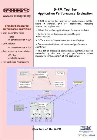
What is DYNES? Dynamic network circuit provisioning and scheduling A distributed virtual cyber-instrument for the creation of virtual circuits on demand between DYNES sites. DYNES spans about 40 US universities and 11 Internet2connectors and interoperates with ESnet, GEANT, APAN, USLHCNet, and many others. Synergetic projects include OliMPS and ANSE. Shawn McKee / CHEP2013
Uses For DYNES Shawn McKee / CHEP2013
Limitations Using Virtual Circuits • As we brought up DYNES sites and began testing we noticed a very important practical limitation in using virtual circuits • A virtual circuit of a specific size would be created • An application would send data on the circuit • The throughput achieved was significantly less than the reserved bandwidth, often less than 50% • What was wrong? Shawn McKee / CHEP2013
Exploring the Problem • DYNESextended the ability to create virtual circuits from the research and education network backbones out to end-sites, where scientists host their data and computing resources • Problem 1: The VCs created were intended to be end-to-end but practical implementation considerations often resulted in portions of the network path not protecting DYNES flows • Reservations of X bandwidth are not typically guaranteed along every part of the path between DYNES sites • One reason DYNES flows may not be able to utilize the bandwidth they have reserved is because they are traversing portions of the path that are congested, resulting in packet loss • Problem 2:The mismatch between the network interface card (NIC) bandwidth on the end-hosts and the amount of reserved bandwidth in the circuit cause micro-bursts of traffic to overrun what the VC can handle, resulting in packet loss or packet re-ordering. (More on this in the next slide) • Either problem causes TCP to deliver much less throughput than was reserved Shawn McKee / CHEP2013
DYNES Bandwidth Guarantees via OSCARS • OSCARSprovides bandwidth guarantees, via QoS, for supported hardware. • OSCARS installs mechanisms on network devices that prioritizes VC traffic up to the bandwidth limit requested. • This can be modeled into two basic classes of service: • Expedited Traffic (traffic in the VC) • Best Effort Traffic (all other traffic) • The QoSmechanism features another behavior that kicks in if the VC tries to use more bandwidth than was requested: • Assume the application using the VC tries to push 2.5Gbps of traffic through a2Gbps reservation. 2Gbps of the traffic will continue to be treated as expedited, but the remaining 0.5Gbps will be sent into a 3rd queue: less than best effort service. • This queue is treated on a lower priority than regular traffic on the interface. On a heavily loaded interface; there is the potential to disrupt the flow and have some packets arrive out of order. • Let’s demonstrate the problem Shawn McKee / CHEP2013
The DYNES OSCARS Circuit GUI Shawn McKee / CHEP2013
Setup Circuit Wisconsin to TTU Shawn McKee / CHEP2013
Circuit Details for Successful Setup Shawn McKee / CHEP2013
Adding Machines to Circuit via VLANs and Private Address Space • For what follows we setup a 1 Gbps VC (steps as above) • VLANs we care about are: • Texas Tech University = 3021 • University of Wisconsin = 3123 • We need to associate one of the server’s interfaces with the VLAN. We do the followingat Texas Tech: sudo /sbin/vconfig add eth0 3021 sudo /sbin/ifconfig eth0.3021 10.10.200.10/24 up sudo /sbin/ifconfig eth0.3021 txqueuelen10000 • Similarly at Wisconsin: sudo /sbin/vconfig add eth0 3123 sudo /sbin/ifconfig eth0.3123 10.10.200.20/24 up sudo /sbin/ifconfig eth0.3123 txqueuelen 10000 Shawn McKee / CHEP2013
Verifying the Circuit Data-Plane • We can do a simple test to check connectivityfrom Wisconsin ping -c 5 10.10.200.10 PING 10.10.200.10 (10.10.200.10) 56(84) bytes of data. 64 bytes from 10.10.200.10: icmp_seq=1 ttl=64 time=36.3 ms 64 bytes from 10.10.200.10: icmp_seq=2 ttl=64 time=36.3 ms 64 bytes from 10.10.200.10: icmp_seq=3 ttl=64 time=36.2 ms 64 bytes from 10.10.200.10: icmp_seq=4 ttl=64 time=36.3 ms 64 bytes from 10.10.200.10: icmp_seq=5 ttl=64 time=36.2 ms --- 10.10.200.10 ping statistics --- 5 packets transmitted, 5 received, 0% packet loss, time 4005ms rtt min/avg/max/mdev = 36.296/36.313/36.352/0.209 ms • We see a latency that matches the distance, and we are able to see that the subnet definitions are correct. Shawn McKee / CHEP2013
Testing the Circuit • We initiate a test using the nuttcp [nuttcp] tool, from the Wisconsin end, sending to Texas Tech. The Texas Tech end is running a server: [dynes@fdt-texastech ~]$ nuttcp -S -p 5679 -P 5678 --nofork • The Wisconsin end is running the client: [dynes@fdt-wisc ~]$ nuttcp -T 30 -i 1 -p 5679 -P 5678 10.10.200.10 1.6875 MB / 1.00 sec = 14.1543 Mbps 9 retrans 1.6875 MB / 1.00 sec = 14.1558 Mbps 3 retrans 1.3750 MB / 1.00 sec = 11.5345 Mbps 0 retrans 1.9375 MB / 1.00 sec = 16.2529 Mbps 0 retrans 3.1250 MB / 1.00 sec = 26.2147 Mbps 0 retrans 1.4375 MB / 1.00 sec = 12.0585 Mbps 21 retrans 2.7500 MB / 1.00 sec = 23.0691 Mbps 0 retrans 3.2500 MB / 1.00 sec = 27.2629 Mbps 8 retrans 1.4375 MB / 1.00 sec = 12.0585 Mbps 0 retrans 2.7500 MB / 1.00 sec = 23.0688 Mbps 0 retrans 2.6250 MB / 1.00 sec = 22.0198 Mbps 37 retrans 0.5625 MB / 1.00 sec = 4.7185 Mbps 0 retrans 2.4375 MB / 1.00 sec = 20.4474 Mbps 0 retrans 3.0000 MB / 1.00 sec = 25.1658 Mbps 20 retrans 0.5000 MB / 1.00 sec = 4.1943 Mbps 0 retrans 2.6250 MB / 1.00 sec = 22.0197 Mbps 0 retrans 3.3750 MB / 1.00 sec = 28.3118 Mbps 13 retrans 1.8125 MB / 1.00 sec = 15.2046 Mbps 0 retrans 3.3125 MB / 1.00 sec = 27.7867 Mbps 0 retrans 3.8125 MB / 1.00 sec = 31.9824 Mbps 0 retrans 5.7500 MB / 1.00 sec = 48.2347 Mbps 0 retrans 3.4375 MB / 1.00 sec = 28.8354 Mbps 14 retrans 3.3125 MB / 1.00 sec = 27.7872 Mbps 0 retrans 4.5625 MB / 1.00 sec = 38.2728 Mbps 23 retrans 1.5625 MB / 1.00 sec = 13.1071 Mbps 0 retrans 3.2500 MB / 1.00 sec = 27.2630 Mbps 0 retrans 4.3125 MB / 1.00 sec = 36.1759 Mbps 23 retrans 83.7159 MB / 30.45 sec = 23.0658 Mbps 0 %TX 0 %RX 171 retrans 36.69 msRTT • The performance does not look good considering that we had requested 1Gbps speeds on the circuit. Shawn McKee / CHEP2013
Examining the Details We can use tcpdump to capture the packets for this test We can then plot the results using tcptrace to examine the details This graph plots sequence number over time, e.g. a linear graph indicates smooth sailing from a transmission perspective. The blips of activity are related to the trouble we saw with nuttcp; each indicates a stall in the process. Shawn McKee / CHEP2013
Zoom in on the Stalls • This indicates stalls or drops of data packets, which delays TCP. The sending end compensates by trying to recover with sending duplicate data into the network, which stalls things further. We end up in a continuous cycle, which reduces our throughput. We have surmised that this is being caused by a three factors: • NICs on sending hosts with much higher speeds than VC • Low buffering (128K) on some switches in the path • QoS provided by the switches in the path causing reordering Shawn McKee / CHEP2013
Exploring Solutions • What can we do to improve the situation? • We initially tried tuning the network stack to match the bandwidth-delay product. • No significant improvement • Some of our applications (e.g., FDT, nuttcp) support “pacing” the application send rate • Some minor improvement but issue seems to be lack of control over how the hardware actually ends up sending packets • We then looked into tcwhich is part of the iptables package in many Linux distributions Shawn McKee / CHEP2013
Using ‘tc’ • tc is used to show and manipulate traffic control settings within the Linux operating system. • Essentially, we create queues on the host interface (similar to network device QoS) to categorize traffic. • With queuing we determine the way in which data is sent; it is important to realize that we can only shape data that we transmit. • While tc has many capabilities, for our use-case we plan to use a simple Hierarchical Token Bucket (HTB) queue and configure traffic rates that are slightly below the requested circuit capacity Shawn McKee / CHEP2013
Trying TC With this in mind, we institute a tc rule that will limit our throughput to 900Mbps (under our reservation of 1 Gbps). Note that this is done on the Wisconsin side: sudo /usr/sbin/tcqdisc del dev eth0.3123 root sudo /usr/sbin/tcqdisc add dev eth0.3123 handle 1: root htb sudo /usr/sbin/tc class add dev eth0.3123 parent 1: classid 1:1 htb rate 112.5mbps sudo /usr/sbin/tc filter add dev eth0.3123 parent 1: protocol ipprio 16 u32 match ipsrc 10.10.200.20/32 flowid 1:1 Note shaping rate is specified as Mbytes/sec but shown in the TC rule as mbps (=MB/sec) After adding this rule, we run the client again, and see the following performance (next slide) Shawn McKee / CHEP2013
TC Test Results [dynes@fdt-wisc ~]$ nuttcp -T 30 -i 1 -p 5679 -P 5678 10.10.200.10 2.1875 MB / 1.00 sec = 18.3486 Mbps 0 retrans 8.3125 MB / 1.00 sec = 69.7281 Mbps 1 retrans 28.3125 MB / 1.00 sec = 237.5170 Mbps 0 retrans 99.1875 MB / 1.00 sec = 832.0559 Mbps 0 retrans 108.5000 MB / 1.00 sec = 910.1831 Mbps 0 retrans 108.4375 MB / 1.00 sec = 909.6078 Mbps 0 retrans 108.4375 MB / 1.00 sec = 909.6706 Mbps 0 retrans 108.4375 MB / 1.00 sec = 909.6215 Mbps 0 retrans 108.3125 MB / 1.00 sec = 908.5747 Mbps 0 retrans 108.3750 MB / 1.00 sec = 909.1354 Mbps 0 retrans 108.3750 MB / 1.00 sec = 909.1363 Mbps 0 retrans 108.2500 MB / 1.00 sec = 908.0605 Mbps 0 retrans 108.3750 MB / 1.00 sec = 909.1218 Mbps 0 retrans 108.3125 MB / 1.00 sec = 908.5911 Mbps 0 retrans 108.3125 MB / 1.00 sec = 908.5902 Mbps 0 retrans 108.4375 MB / 1.00 sec = 909.6133 Mbps 0 retrans 108.5000 MB / 1.00 sec = 910.1731 Mbps 0 retrans 108.4375 MB / 1.00 sec = 909.6533 Mbps 0 retrans 108.3750 MB / 1.00 sec = 909.1199 Mbps 0 retrans 108.4375 MB / 1.00 sec = 909.6388 Mbps 0 retrans 108.3750 MB / 1.00 sec = 909.1154 Mbps 0 retrans 108.4375 MB / 1.00 sec = 909.6406 Mbps 0 retrans 108.3750 MB / 1.00 sec = 909.1154 Mbps 0 retrans 108.3125 MB / 1.00 sec = 908.5911 Mbps 0 retrans 108.4375 MB / 1.00 sec = 909.6388 Mbps 0 retrans 108.5000 MB / 1.00 sec = 910.1640 Mbps 0 retrans 108.3125 MB / 1.00 sec = 908.5593 Mbps 0 retrans 108.5000 MB / 1.00 sec = 910.1967 Mbps 0 retrans 108.4375 MB / 1.00 sec = 909.6397 Mbps 0 retrans 108.3125 MB / 1.00 sec = 908.5911 Mbps 0 retrans 2965.6678 MB / 30.12 sec = 825.9052 Mbps 3 %TX 8 %RX 1 retrans36.73 msRTT Very close to the 900 Mbps shaped request. This works much better. Retry with 1000 Mbps TC config next Shawn McKee / CHEP2013
Next TC Test at 1 Gbps dynes@fdt-wisc ~]$ nuttcp -T 30 -i 1 -p 5679 -P 5678 10.10.200.10 2.8750 MB / 1.00 sec = 24.1153 Mbps 0 retrans 6.8125 MB / 1.00 sec = 57.1492 Mbps 3 retrans 15.1250 MB / 1.00 sec = 126.8811 Mbps 8 retrans 17.1875 MB / 1.00 sec = 144.1652 Mbps 0 retrans 19.0625 MB / 1.00 sec = 159.9147 Mbps 0 retrans 22.5000 MB / 1.00 sec = 188.7422 Mbps 0 retrans 29.4375 MB / 1.00 sec = 246.9406 Mbps 0 retrans 31.9375 MB / 1.00 sec = 267.9114 Mbps 6 retrans 15.8125 MB / 1.00 sec = 132.6459 Mbps 0 retrans 21.5625 MB / 1.00 sec = 180.8795 Mbps 0 retrans 24.6875 MB / 1.00 sec = 207.0925 Mbps 0 retrans 30.2500 MB / 1.00 sec = 253.7435 Mbps 0 retrans 39.7500 MB / 1.00 sec = 333.4735 Mbps 0 retrans 44.0000 MB / 1.00 sec = 369.1102 Mbps 7 retrans 21.6875 MB / 1.00 sec = 181.9228 Mbps 0 retrans 29.3750 MB / 1.00 sec = 246.4070 Mbps 0 retrans 32.1250 MB / 1.00 sec = 269.4830 Mbps 0 retrans 37.8750 MB / 1.00 sec = 317.7239 Mbps 0 retrans 46.9375 MB / 1.00 sec = 393.7466 Mbps 0 retrans 57.3750 MB / 1.00 sec = 481.2993 Mbps 0 retrans 31.8750 MB / 1.00 sec = 267.3751 Mbps 4 retrans 33.9375 MB / 1.00 sec = 284.6907 Mbps 0 retrans 36.8750 MB / 1.00 sec = 309.3503 Mbps 0 retrans 41.1250 MB / 1.00 sec = 344.9805 Mbps 0 retrans 48.9375 MB / 1.00 sec = 410.5187 Mbps 0 retrans 18.3750 MB / 1.00 sec = 154.1303 Mbps 9 retrans 27.8125 MB / 1.00 sec = 233.2900 Mbps 0 retrans 30.0000 MB / 1.00 sec = 251.6952 Mbps 0 retrans 35.6875 MB / 1.00 sec = 299.3684 Mbps 0 retrans 44.0625 MB / 1.00 sec = 369.6230 Mbps 0 retrans 906.7649 MB / 30.28 sec = 251.2284 Mbps 0 %TX 3 %RX 37 retrans36.71 msRTT We see a problem again! Shawn McKee / CHEP2013
TC Summary and RoCE • Using tc to shape application traffic destined for a DYNES virtual circuit can significantly improve the efficiency of using that circuit. • tc is available already on most Linux distributions • We have also begun to explore using RDMA or Converged Ethernet (RoCE) as another option which shows great promise for “clean” network paths. • RoCEhas been demonstrated to achieve 99% of the underlying circuit bandwidth BUT it requires a lossless path to work well. Shawn McKee / CHEP2013
Conclusion • Virtual circuits are an interesting option to help manage our infrastructure and support sensitive or high-priority tasks • Using virtual circuits efficiently requires that we appropriately modify how we use the network. • Using ‘tc’, available in most linuxdistros as part of iptables, allows us to shape our network traffic to efficiently use bandwidth made available via virtual circuits • Additional options like RDMA over Converged Ethernet (RoCE) also show promise in being able to efficiently use bandwidth provided by virtual circuits Shawn McKee / CHEP2013
Useful Links The DYNES web-page at Internet2: http://www.internet2.edu/ion/dynes.html We have a DYNES user guide at: http://www.internet2.edu/ion/docs/20130108-DYNESGuide.pdf Subscribe to the DYNES user mailing list at https://lists.internet2.edu/sympa/subscribe/dynes-users Email questions to dynes-questions@internet2.edu Packet pacing http://fasterdata.es.net/host-tuning/packet-pacing/ Using ‘tc’ whitepaper http://fasterdata.es.net/assets/fasterdata/Using-tc-with-OSCARS-curcuits.pdf Shawn McKee / CHEP2013
Questions or Comments? Shawn McKee / CHEP2013
Additional Slides Shawn McKee / CHEP2013
DYNES Deployment Diagram Shawn McKee / CHEP2013
DYNES Status The DYNES project (an NSF MRI 3 year grant) was completed on July 31. Last set of sites were installed in Spring 2013 We have deployed all of the DYNES planned footprint and upgraded a subset of sites with Openflow capable switches We are continuing to work on some remaining issues with the reliability and speed of VC creation between DYNES sites Shawn McKee / CHEP2013