Download
1 / 30
300 likes | 395 Views
ILC Accelerator Activities in North America (cooperation with France ). Presentation at IRFU Linear Collider Days prepared by: Marc Ross ( SLAC ) November 29, 2013. Completing the ILC Technical Design Phase. January 2013. TDP Goals:

E N D
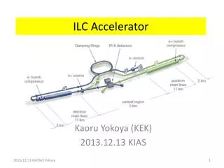
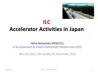
ILC Accelerator Activities in North America(cooperation with France) Presentation at IRFU Linear Collider Days prepared by: Marc Ross (SLAC) November 29, 2013 2013 IRFU Linear Collider Days
Completing the ILC Technical Design Phase January 2013 • TDP Goals: • R & D to enable Project Proposal and updated Value estimate – with Cost Containment • SC RF Technology Transfer • development of a strong industrial base • Technical Design Report: • Consists of two parts: 1) R & D Report and 2) Design Description • Beam Test Facilities: • SRF Linac: Fermilab NML, DESY E-XFEL and FLASH, KEK STF • Beam Dynamics: Cornell CesrTA (2008 – 2010) • Beam Tuning: KEK ATF2 • Production / Industrialization: • CEBAF Upgrade and E-XFEL 2013 IRFU Linear Collider Days
Completing the TDP: Outline Present 2013 IRFU Linear Collider Days • TDP Goals: • R & D to enable Project Proposal and updated Value estimate – with Cost Containment • SC RF Technology Transfer • development of a strong industrial base • Technical Design Report: • Consists of two parts: 1) R & D Report and 2) Design Description • Beam Test Facilities: • SRF Linac: Fermilab NML, DESY E-XFEL and FLASH, KEK STF • Beam Dynamics: Cornell CesrTA (2008 – 2010) • Beam Tuning: KEK ATF2 • Production / Industrialization: • CEBAF Upgrade and E-XFEL
ILC Accelerator Activities: Outline By the end of the XFEL Production > 1000 cavities will have been fabricated by industry and processed using the basic TESLA – recipe. • SC RF Technology Transfer • Development of a strong industrial base • Production / Industrialization: • CEBAF Upgrade and E-XFEL • Beam Test Facilities: • SRF Linac: Fermilab NML, DESY E-XFEL and FLASH, KEK STF • Beam Dynamics: Cornell CesrTA (2008 – 2010) • Beam Tuning: KEK ATF2 • US contribution to ‘Linear Collider Collaboration’ (LCC) • ‘P5’ prioritization activity 2013 IRFU Linear Collider Days
EU - XFEL 2013 IRFU Linear Collider Days • Cavity production lines fully functioning: 8 cavities / week • Two companies • Cryomodule production: • Three pre-series CM (XM-3, XM-2, XM-1) in process; typical time to construct 4 months; time to test unknown • Production series of 81 each started Sep. 02, 2013; • One CM / week nominal; one production line (CEA-Saclay) • 24 cavities to be used for high – gradient development • (See E. Elsen)
Jefferson Lab CEBAF 12 GeV Upgrade 'BB Lunch', M. Ross (SLAC)
Slide dated late 09.2013 All C100 cryomodules are now installed (11.2013) 'BB Lunch', M. Ross (SLAC)
SLAC Proposal: 2013 IRFU Linear Collider Days • Following BESAC (Basic Energy Sciences Advisory) report in late July 2013: • Shakeup of US accelerator construction projects: • SLAC LCLS-II project redefined • ANL APS upgrade program redefined • SLAC Proposal: • 4 GeV CW SRF Linac-based FEL • Use ILC / XFEL 1.3 GHz technology • Installed in the upstream 1/3 of the SLAC linac housing • (50 year old S-band linac to be completely removed) • First light end of FY 2019
LCLS-II and ILC • Much LCLS-II construction will be done at Fermilab, using infrastructure intended for ILC • 18 CM? (50%) • Other CM to be made at JLab (and Cornell) • Saclay CM assembly industrial experience unique • US team have made ~ two ILC CM. LCLS-II effort will help understand US-domestic technical, cost, and industrialization
RF Parameters: 2013 IRFU Linear Collider Days
RF Parameters (2) 2013 IRFU Linear Collider Days
LCLS-II - Linac and Compressor Layout for 4 GeV L0 j 0 V0 97 MV L1 j =-26° V0=235 MV HL j =-170° V0 =40 MV L2 j = -28° V0= 1448 MV L3 j = 0 V0= 2460 MV CM01 CM2,3 CM15 CM35 CM04 CM16 3.9GHz LTU 4.0 GeV R56 = 0 Ipk = 1000 A Lb = 0.024 mm sd 0.02 % LH 98 MeV R56 = -5 mm Ipk = 12 A Lb = 2.0 mm sd = 0.006 % BC1 270 MeV R56 = -65 mm Ipk = 60 A Lb = 0.40 mm sd = 1.4 % BC2 1550 MeV R56 = -65 mm Ipk = 1000 A Lb = 0.024 mm sd = 0.50 % GUN 0.75 MeV 100 pC; Machine layout 26SEP2013; Bunch length Lb is FWHM Includes 2-km RW wake 2013 IRFU Linear Collider Days * L0 phases: (-40, -52, 0, 0, 0, 13, 33), with cav-2 at 20% of other L0 cav’s.
First 800 m of SLAC linac (1964): 350 m September 6, 2013 Marc Ross, SLAC LCLS-II
ILC R & D initiative: Power Coupler development • Mandated by PAC (12.2012) technical review • Common activity with Orsay /LAL • Issues: • Cost • Copper coating / flaking • Complex Assembly • Plug-compatibility
(1) Deep Technical Review of Input Couplers TTF3/XFEL coupler TDR coupler STF-2 coupler
ILC specification • Power requirements • We recommend to match the coupler to 30 MV/m for reduced filling time and smaller Qext range • Max coupler power at operation 450 kW (for 8.8 mA, 10Hz, Eacc=31.5 MV/m ±20%) • RF processing to at least four times max input power ~ 1.8 MW up to 500 us at test stand TW • Surface field not a problem for both designs, i.e. 40mm and 60mm are both ok • Should check flattop regulation at 25 MV/m and Qext ~ 1e7 (LFD) • TW testing on test stand up to 1.8MW has to be done for both: TTF3 and STF2 • Q-ext • Variable coupling is needed, remote operation • QL tuning range: 2-7x10⁶ is needed, but we recommend 1-10 x 106 • 1-10∙106 is achieved with TTF3 • STF2 has to be improved • Antenna alignment: • Design should be +-2mm • For TTF3 coupler the most sensitive parameter is a horizontal antenna shift/tilt. 3mm shift change QL by ~20%. Vertical tolerances are relaxed. • For STF-2 coupler this is not issue, mechanical design guarantee small shift. • TTF3 has to be improved
Cryogenic loss: • Coupler contribution to cryogenic losses at 2K is ~5%. = not critical. • Major contribution from coupler is 70K • Conditioning time • Both designs are ok • The nominal conditioning time of < 50h is achieved/demonstrated. • Multipacting • DESY and SLAC simulations, tests and operation show no problem with TTF3 • STF2 will be simulated, tests show no problem • One vs. two windows • Many single window coupler are successful under operation • The single window would need to seal-off the cavity before the cavity-string installation into the cryomodule. • Single window coupler for ILC would need complete new development and test program of coupler (and module) • But it could be a significant cost saving • Compatibility • Cavity and attached parts (power coupler, tuner, HOM coupler, feedthroughs, He vessel, thermal connections, magnetic shield…) are tuned/balanced, it is not easy to exchange only parts of this composition • STF2 coupler design does not fit in the compatibility requirements of the TDR (40mm cavity coupler flange)
Cost • CPI: STF2 price is 1.9 higher • Toshiba: STF2 slightly lower price • RI: about same price • Industrial study of STF2 for design optimization and cost reduction is recommended • The TTF3 coupler mass fabrication has to be investigated Recommendation: • STF2 coupler has to demonstrate stable long time (>6 month) beam operation in a CM (TTF3 coupler has a long history in FLASH) • The ILC management recommend an adapted STF2 design with 40mm cavity flange. In this case more development steps have to follow in order to realize the compatible design. The new design has to be proven with beam operation. • The concept of plug compatibility has to be further developed in view of a spare part concept. We recommend spare modules, not individual parts. • An industrial study of mass production for both designs is recommended • Industrial study of STF2 for design optimization and cost reduction is recommended.
ATF2 Program Status Glen White, SLAC January 2013 2013 IRFU Linear Collider Days
Detector measures signal Modulation Depth “M” measurable range determined by fringe pitch depend on crossing angle θ (and λ ) Focused Beam : large M N + Small σy N - [rad] N: no. of Compton photons Convolution between e- beam profile and fringe intensity Dilluted Beam : small M Large σy [rad] 2013 IRFU Linear Collider Days
Expected Performance Measures σy* = 20 nm 〜few μm with < 10% resolution σy and M for each θ mode select appropriate mode according to beam focusing 2013 IRFU Linear Collider Days
Laser transported to IP 174 deg. 30 deg. beam pipe optical delay half mirror 2 - 8 deg • Vertical table • 1.7 (H) x 1.6 (V) m • Interferometer • Phase control (piezo stage) • path for each θ mode • (auto-stages + mirror actuators ) Crossing angle continuously adjustable by prism 2013 IRFU Linear Collider Days
beforehand …. Construct & confirm laser paths, timing alignment Role of IPBSM in Beam Tuning precise position alignment by remote control Longitudinal:z scan transverse :laser wire scan laser spot size σt,laser = 15 – 20 μm After all preparations ………. continuously measure σy using fringe scans Feed back to multi-knob tuning 2013 IRFU Linear Collider Days
Beam time status in 2012 Spring run Feb; 30 deg mode commissioned ( 1st M detection on 2/17) stable measurements of M 〜 0.55 • 2 - 8 ° mode: clear contrast (Mmeas ~0.9) • Prepared 174 deg mode commissioning M=0.52 ±0.02 (stat) σy=166.2 ±6.7 (stat) [nm] (10 x bx*, 3 x by* optics) preliminary Major optics reform of 2012 summer 12/20 : 1st success in M detection at 174 deg mode By IPBSM group@KEK • Suppress systematic errors • Higher laser path stability / reliability 10 x βx* , 1 x βy* preliminary Last 2 days in Dec run Measured many times M = 0.15 – 0.25 (correspond to σy 〜 70 – 82 nm) Large step towards achieving ATF2 ‘s goal !! error studies ongoing aimed at deriving “true beamsize” Winter run • High M measured at30 ° mode • Contribute with stable operation to ATF2 beam focusing / tuning study * IPBSM systematic errors uncorrected ** under low e beam intensity (〜 1E9 e / bunch) 2013 IRFU Linear Collider Days
Beam time status in 2013 Spring Stable IPBSM performance major role in beam tuning measured M over continuous reiteration of linear /nonlinear@ tuning knobs @ 174 ° mode preliminary 10 x bx*, 1 x by* dedicated data for error studies under analysis 174 ° mode ”consistency scan” measure M vs time after all conditions optimized M 〜 0.306 ±0.043 (RMS) correspond to σy 〜 65 nm Best record preliminary ex) consecutive 10 fringe scans from Okugi-san’s Fri operation meeting slides Time passed moving towards goal of σy = 37 nm : higher IPBSM precision and stability & looser current limits of normal / skew sextupoles current 2013 IRFU Linear Collider Days
The Reality… May 2 week Cont. Run • Summary of all scans during 2 week ops period • Summary plot courtesy of Edu. 2013 IRFU Linear Collider Days