Download
1 / 37
370 likes | 382 Views
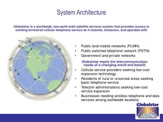
Telephone Network & Signaling System. 8.2 Telephone Network. Major Components LATAs Making a Connection Analog Services Digital Services A Brief History. Figure 8.11 A telephone system. Note :.

E N D
8.2 Telephone Network Major Components LATAs Making a Connection Analog Services Digital Services A Brief History
Note: Intra-LATA services are provided by local exchange carriers. Since 1996, there are two types of LECs: incumbent local exchange carriers and competitive local exchange carriers.
Note: Voice communication used analog signals in the past, but is now moving to digital signals. On the other hand, dialing started with digital signals (rotary) and is now moving to analog signals (touch-tone).
T1 Channel Bank Analog Voice Lines Each analog voice line (Channel) issampled 8,000/s (resolution is 8 bits) 125 micro sec. 1 2 3 . . 24 TDM 24 23 22 . . . 3 2 1 F 24 Digital Channelswith Framing bit F. Channel Bank for 24 AnalogLines with Analog to Digital Conversion Local Loop DS0 = 8,000x8=64 kb/s DS1 = 24 DS0 + 8 kb/s DS1 = 1,536+8 = 1.544 kb/s TDM … Time Division Multiplexing
Digital Switching T1 or DS-1 Transmission Frame (US) • Bit 193 (F) is framing bit, used for synchronization • Voice channels: 7-bit PCM, bit 8 is a signaling bit • Data channels: bit 8 of Ch 24 is used for control(8 kb/s) reducing capacity to 56 kb/s. 125 micro seconds Channel 1 Channel 2 Channel 24 ...... 1 2 3 4 5 6 7 8 1 2 3 4 5 6 7 8 F1 2 3 4 5 6 7 8 193 bits
Digital Hierarchy (US, EU) Carrier Channels Data Rate DS-0 1 .064 Mb/s DS-1 T1 24 1.544 Mb/s DS-2 T2 96 6.312 Mb/s DS-3 T3 672 44.736 Mb/s E1 30 2.048 Mb/s E2 120 8.448 Mb/s E3 480 34.368 Mb/s
Optical Hierarchy Optical Electrical Rate • OC-1 STS-1 51 Mb/s • OC-3 3 x STS-1 3 x 51 Mb/s • OC-3c STS-3 155 Mb/s • OC-12 STS-12 622 Mb/s • OC-24 STS-24 1.2 Gb/s • OC-48 STS-48 2.5 Gb/s • OC-192 STS-192 10 Gb/s Note: OC and STS circuits are usually used with SONET (Synchronous Optical NETwork)
Signaling • Signaling is a technical term used by the telephone industry. • Signaling is a set of protocols and associated data exchange for managing the telephone network: • A signal to indicate Off- and On-Hook condition of the telephone set • Transmission of dial tones, busy tones, ringing signal, Caller ID service, etc. • Transmission of inter-exchange data for rerouting calls, diagnostics information, etc. • Transmission business information for billing and accounting.
Control Signaling Functions • Audible communication with subscriber • Transmission of dialed number • Call can not be completed indication • Call ended indication • Signal to ring phone • Billing info • Equipment and trunk status info • Diagnostic info • Control of specialist equipment
Control Signal Sequence • Both phones on hook • Subscriber lifts receiver (off hook) • End office switch signaled • Switch responds with dial tone • Caller dials number • If target not busy, send ringer signal to target subscriber • Feedback to caller • Ringing tone, engaged tone, unobtainable • Target accepts call by lifting receiver • Switch terminates ringing signal and ringing tone • Switch establishes connection • Connection release when Source subscriber hangs up
Switch to Switch Signaling • Subscribers connected to different switches • Originating switch seizes interswitch trunk • Send off hook signal on trunk, requesting digit register at target switch (for address) • Terminating switch sends off hook followed by on hook (wink) to show register ready • Originating switch sends address
Location of Signaling • Subscriber to network • Depends on subscriber device and switch • Within network • Management of subscriber calls and network • More complex
Sig Sig Office A Office B Sig Sig Inband Signaling • Inband (or inchannel) signaling transmits control signals in the same channel used by the customer voice (or data) signals • Simple but exposed to fraud
Inband Signaling Call Set Up • 20 seconds set-up time • Less efficient trunk occupancy • More vulnerable to fraud on the network • Call Processing Overhead • Fixed Routing Patterns
Out-of-Band Signaling • Transmits control signals using the same facilities as the voice but a different part of the frequency band • Provides for continuous supervision (less fraud) Sig Sig Office A Office B Sig Sig
Out-of-Band Signaling Call Set Up • 1-3 seconds set-up time • Maximize trunk utilization • Highly secure • Minimal switch overhead • Flexible design
Common Channel Signaling Office A Trunks for Voice Office B STP STP Signal Transfer Points SP SP Transmits control signals over dedicated signaling links that are common to a number of voice channels. Signaling System 7 (SS7) is a standard that provides internal control and network intelligence for circuit switched networks. Signal Point SS7
Signaling System 7 • Specified in 1980, updated in 1984 and 1988 • Supports circuit switching and packet switching (e.g., X.25 and Frame Relay) • A very complex piece of software that manages all the switches in the telephone network (over 10 million lines of code) • Installed in the Signal Point (SP) computer network to control the Signal Transfer Point (STP) switches which carry all voice and data traffic
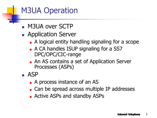
Signaling System 7 • Enhanced services requested by users require bidirectional signaling capabilities, flexibility of call setup and remote database access • With SS7, a signaling channel conveys, by means of labeled messages, signaling information relating to call processing and to network management • SS7 is the most important signaling system in the world: it supervises the PSTN, the cellular networks (GSM), and the Intelligent Network
SS7 in the PSTN Analog SS7 Analog ISDN SS7 ISDN CPE Switch NNI Switch CPE UNI UNI Circuit Switching Network CPE: Customer Premises Equipment UNI: User-Network Interface NNI: Network-Network Interface ISDN: Integrated Services Digital Network
Interface between the circuit switching networkand the signaling network Signaling Links Signaling Point Signaling Point Signaling Network (SS7) Control Unit Control Unit Voice Circuits
Signaling and Switching Planes SP: Signaling Point STP: Signaling Transfer Point Signaling Plane SP SP STP Signaling link SP SP STP Switching Plane Voice circuits
Example of Signaling Network STP STP SP SP SP STP STP ... SP SP Network 1 Network 2
STP STP SP SP
Switch A analyzes the dialed digits and determines that it needs to send the call to switch B. 2. Switch A selects an idle trunk between itself and switch B and formulates an initial address message (IAM), the basic message necessary to initiate a call. The IAM is addressed to switch B. It identifies the initiating switch (switch A), the destination switch (switch B), the trunk selected, the calling and called numbers, as well as other information. 3. Switch A picks one of its a link (e.g., AW) and transmits the message over the link for routing to switch B.
4.STP W receives a message, inspects its routing label, and determines that it is to be routed to switch B. It transmits the message on link BW. 5.Switch B receives the message. On analyzing the message, it determines that it serves the called number and that the called number is idle. 6. Switch B formulates an address complete message (ACM), which indicates that the IAM has reached its proper destination. The message identifies the recipient switch (A), the sending switch (B), and the selected trunk.
7. Switch B picks one of the links (e.g., BX) and transmits the ACM over the link for routing to switch A. At the same time, it completes the call path in the backwards direction (towards switch A), sends a ringing tone over that trunk towards switch A, and rings the line of the called subscriber. 8. STP X receives the message, inspects its routing label, and determines that it is to be routed to switch A. It transmits the message on link AX. 9. On receiving the ACM, switch A connects the calling subscriber line to the selected trunk in the backwards direction (so that the caller can hear the ringing sent by switch B). 10. When the called subscriber picks up the phone, switch B formulates an answer message (ANM), identifying the intended recipient switch (A), the sending switch (B), and the selected trunk.
11. Switch B selects the same A link it used to transmit the ACM (link BX) and sends the ANM. By this time, the trunk also must be connected to the called line in both directions (to allow conversation). 12. STP X recognizes that the ANM is addressed to switch A and forwards it over link AX. 13. Switch A ensures that the calling subscriber is connected to the outgoing trunk (in both directions) and that conversation can take place. 14. If the calling subscriber hangs off first (following the conversation), switch A will generate a release message (REL) addressed to switch B, identifying the trunk associated with the call. It sends the message on link AW.
15. STP W receives the REL, determines that it is addressed to switch B, and forwards it using link WB. 16. Switch B receives the REL, disconnects the trunk from the subscriber line, returns the trunk to idle status, generates a release complete message (RLC) addressed back to switch A, and transmits it on link BX. 17. STP X receives the RLC, determines that it is addressed to switch A, and forwards it over link AX. 18. On receiving the RLC, switch A idles the identified trunk.
STP SCP
Asubscriber served by switch A wants to reserve a rental car at a company’s nearest location. She dials the company’s advertised 800 number. • 2. When the subscriber has finished dialing, switch A recognizes that this is an 800 call and that it requires assistance to handle it properly. • 3. Switch A formulates an 800 query message including the calling and called number and forwards it to either of its STPs (e.g., X) over a link to that STP (AX). • 4. STP X determines that the received query is an 800 query and selects a database suitable to respond to the query (e.g., M).
5. STP X forwards the query to SCP M over the appropriate link (MX). SCP M receives the query, extracts the passed information, and (based on its stored records) selects either a real telephone number or a network (or both) to which the call should be routed. 6. SCP M formulates a response message with the information necessary to properly process the call, addresses it to switch A, picks an STP using a link (e.g., MW), and routes the response. 7. STP W receives the response message, recognizes that it is addressed to switch A, and routes it to A over AW. 8. Switch A receives the response and uses the information to determine where the call should be routed. It then picks a trunk to that destination, generates an IAM, and proceeds (as it did in the previous example) to set up the call.