Download
1 / 61
650 likes | 806 Views
Chips developed at CERN in the framework of the Medipix3 Collaboration. R. Ballabriga, J. Alozy, M. Campbell, E. Frojdh , M. De Gaspari, E.H.M. Heijne, S. Kulis, X . Llopart, T. Poikela, L.Tlustos , P. Valerio and W.Wong CERN, PH Department 1211 Geneva 23 Switzerland.

E N D
Chips developed at CERN in the framework of the Medipix3 Collaboration R. Ballabriga, J. Alozy, M. Campbell, E. Frojdh, M. De Gaspari, E.H.M. Heijne, S. Kulis, X. Llopart, T. Poikela, L.Tlustos, P. Valerio and W.Wong CERN, PH Department 1211 Geneva 23 Switzerland
Hybrid pixel detector • Possible radiation measurements on-pixel • Readout architecture
Hybrid pixel detector illustration • The detector can be optimized for the application • Standard CMOS process
Possible on-pixel radiation measurements Preamplifier Digital pulse processing circuitry Comparator Shaper vOUTpreamp vOUTpreamp Thr time Photon Counting (PC) N hits/pixel/unit time (imaging) Time over Threshold (ToT) Q Charge/hit (deposited charge measurement in sparse frames, allows subpixel spatial resolution) Time of Arrival (ToA) (relative to Shutter end) T time (time measurement. Allows correlation between events, event-BX, 3D reconstruction in gas detectors) t0 t1 t2 t3 t4 t5 t6 t7 t8 t9 t10 t11 t12 t13 t14 Time of Arrival (ToA) (latching the time variable into a register) latch t1
Readout time vs frame occupancy for different readout architectures 0.1% 1% 5% 20% compression X. Llopart Simulation with 100MHz clock, 256x256 pixel matrix, 16 bits/pixel, randomly distributed hits. Full Frame Readout: 256x256x16 bits are read out. Event-by-event (zero suppressed): for each pixel hit, we read out 16bits for the content and 16 bits for the pixel address. Zero compression: columns and pixels that did not register events are skipped.
Medipix related hybrid pixel readout chips 1mm SACMOS Medipix1 (1998) 0.25mm CMOS Medipix2 (2001) Timepix (2006) 0.13mm CMOS Covered in detail Lessons learnt from Medipix3.0 Medipix3 (2009) Dosepix (2011) M. De Gaspari: “Design of the analog front end for the timepix3 detector and smallpix hybrid pixel detectors in 130nm CMOS technology” T. Poikela “Digital column readout architectures for hybrid pixel detector readout chips” P. Valerio: “A prototype hybrid detector pixel ASIC for a CLIC experiment” Timepix3 (2013) Velopix Smallpix 65nm CMOS Clicpix prototype (2013)
Medipix related hybrid pixel readout chips 1mm SACMOS, 64x64 pixels, 170x170mm2 PC / Frame based readout Medipix1 (1998) 0.25mm CMOS, 256x256 pixels, 55x55mm2 PC / Frame based readout Medipix2 (2001) 0.25mm CMOS, 256x256 pixels, 55x55mm2 PC, ToT, ToA / Frame based readout Timepix (2006) 0.13mm CMOS, 256x256 pixels, 55x55mm2 PC / Frame based readout Event by event charge reconstruction and allocation Medipix3 (2009) 0.13mm CMOS, 16x16 pixels, 220x220mm2 ToT, PC / Rolling shutter (programmable column readout) Event by event binning of energy spectra (16 digital thrs) Dosepix (2011) 0.13mm CMOS, 256x256 pixels, 55x55mm2 PC; ToT, ToA (simultaneous)/ Data driven readout Timepix3 (2013) 0.13mm CMOS, 256x256 pixels, 55x55mm2, ToA, Binary/ToT (TBD), Data driven readout Velopix 0.13mm CMOS, 512x512 pixels, 40x40mm2 (TBD), TSV compatible PC, iToT; ToA, ToT1 (simultaneous)/ Frame based (ZC) Smallpix 65nm CMOS, 64x64 pixels, 25x25mm2 ToA, ToT1 (simultaneous)/ Frame based (ZC) Clicpix prototype (2013)
Cross section of a Hybrid Pixel Detector system (X-ray photon energy deposition) A. B. g g The signal from a photon is induced in one pixel The signal for one photon is shared between two pixels if the photon deposits its energy at the pixel edges Sensor dimensions to scale (55mm pixel pitch, 300mm thicksensor)
Motivation for the Medipix3 chip • Simulated Data • Si 300mm, 55mm pixel • 10keV monochromatic photon beam • Charge diffusion produces “charge sharing” tail Simulation: L. Tlustos
Absorption efficiency for Si is low in the energy range for diagnostic radiography Energy range for diagnostic radiography
The absorption efficiency depends on Z Energy range for diagnostic radiography
The absorption efficiency depends on Z Energy range for diagnostic radiography
The absorption efficiency depends on Z Energy range for diagnostic radiography
Fluorescence in high-Z materials g Primary photon releases photoelectron that loses its energy generating electron-hole pairs De-excitation of the first atom releases a characteristic photon that will deposit its energy some distance away from the first interaction Multiple hits can be detected for a single incoming photon gf 2. 1. 3.
Fluorescence in high-Z materials Mean free path of fluorescence photon [mm] Fluorescence yield [%] Energy fluorescence photons [keV] Z The mean free path of the fluorescence photons is in the same order of magnitude as the pixel pitch The fluorescence yield increases with the atomic number Table: L. Tlustos, PhDthesis
Motivation for the Medipix3 chip • Simulated data • CdTe300mm • 110mm pixel pitch • 40keV monochromatic beam • The influence of fluorescence photons in the energy spectrum is seen Simulation: L. Tlustos
The algorithm for charge reconstruction and hit allocation: Charge Summing Mode 1. TH0 is applied to the local signal 2. Arbitration circuitry identifies the pixel with largest charge and supresses the pixels with lower signal 3. In parallel, the charge has been reconstructed in the analog summing circuits 4. The pixel with highest charge checks the adjacent summing circuits to see if at least one of them exceeds TH1 Advantage of small pixels without disadvantage of charge sharing
Medipix3RX Pixel Diagram: Charge Summing Mode If(LocalCharge>ChargeNeighbours) Then Counter0++ Local charge to adjacent pixels CF DataIn1 DataIn0 DiscOutNeighbours ToNeighbours 3 8 8 Local charge 1 gm -Av Arbitration logic Counter0 DiscOutLocal 1 1 THspm 1 CTEST Single Pixel Mode Arbitrated 1 1 TestBit TestPulse Reconstructed charge 1 Charge from adjacent pixels synchronization Counter1 DiscOutSum 1 3 THcsm 1 Charge Summing Mode 3 1 If((LocalCharge>ChargeNeighbours) and (Reconstructed charge in one of the adjacent summing circuits > THCSM)) Then Counter1++ 1 DiscOutSumNeighbours DataOut1 DataOut0
Medipix3RX Modes of Operation Linearity Noise Thdispersion
Medipix3RX regular structure layout A1 to A4: analog circuitry of pixels 1 to 4 respectively D12: digital part of pixels 1-2 D34: digital part of pixels 3-4 Digital part designed using standard digital flow using a high density - low power transistors library 110mm
Measurement of 10KeV monochromatic light Derivative of the total number of counts in the matrix as a function of the threshold Full matrix measurement, Raw data, No offline pixel realignment In Charge Summing Mode the energy is reconstructed and each photon is counted once E. Fröjdh
Measurement (60keV, 110mm pitch, 2mm CdTe) ~4.4KeV FWHM Fluorescence photons are included in charge sum if their deposition takes place within the volume of the pixels neighbouring the initial deposition T. Koenig
Medipix3RX electrical characterization: measurements obtained (chip with sensor) *Measurements with CdTe, 2mm thick at 110mm pitch (paralizable model fit)
How imaging can benefit from the Medipix3 architecture: Energy weighting
Energy selective, planar imagingMPX3 CdTe 1mm - Spectroscopic Mode 110µm PiezoLighter Magnification: 1.3x Bias: -320V MPX3 CdTe 1mm Color Mode 4x11 tiles 1 acquisition, 4 thresholds Courtesy S. Procz RGB: 9-50 keV 23-50 keV 9-14 keV 14-23 keV
How imaging can benefit from the Medipix3 architecture: K-edge imaging
CT scan of a sample containing gadolinium and iodine CT of a phantom 0.15s acquisition 720 projections Hounsfield units:
Mass attenuation for different energies: The K-edge for gadolinium is seen in the CSM Courtesy, T. Koenig, KIT
The SNR in CSM is better for high energy photons Courtesy, T. Koenig, KIT
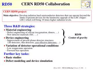
Lessons for hybrid pixel detectors designs • Medipix3.0 was the first large scale mixed-mode chip in 0.13mm in the HEP community • The biasing circuitry in big area chips is susceptible to thin gate oxide damage during processing if the transistors are not protected by tie-down diodes (in spite of being within antenna rules) Lack of protection can generate increased VT mismatch and gate current random telegraphic noise
Lessons for Hybrid pixel detectors • Layout has to be optimized using best layout practices: • Placement of dummy transistors for having equal surroundings for matched transistors • Placement of matched devices symmetrical wrtNwell edges • Segmentation of transistors in the length dimension1 • Placement of symmetrical identical metal coverage on top of matched transistors 1“Methodology to evaluate long channel matching deterioration and effects of transistor segmentation on Mosfet matching” H. Tuinhout et al. 2010 Int. conference on Microelectronic test structures, Hiroshima, Japan
Medipix related hybrid pixel readout chips 1mm SACMOS, 64x64 pixels, 170x170mm2 PC / Frame based readout Medipix1 (1998) 0.25mm CMOS, 256x256 pixels, 55x55mm2 PC / Frame based readout Medipix2 (2001) 0.25mm CMOS, 256x256 pixels, 55x55mm2 PC, ToT, ToA / Frame based readout Timepix (2006) 0.13mm CMOS, 256x256 pixels, 55x55mm2 PC / Frame based readout Event by event charge reconstruction and allocation Medipix3 (2009) 0.13mm CMOS, 16x16 pixels, 220x220mm2 ToT, PC / Rolling shutter (programmable column readout) Event by event binning of energy spectra (16 digital thrs) Dosepix (2011) 0.13mm CMOS, 256x256 pixels, 55x55mm2 PC; ToT, ToA (simultaneous)/ Data driven readout Timepix3 (2013) 0.13mm CMOS, 256x256 pixels, 55x55mm2, ToA, Binary/ToT (TBD), Data driven readout Velopix 0.13mm CMOS, 512x512 pixels, 40x40mm2 (TBD), TSV compatible PC, iToT; ToA, ToT1 (simultaneous)/ Frame based (ZC) Smallpix 65nm CMOS, 64x64 pixels, 25x25mm2 ToA, ToT1 (simultaneous)/ Frame based (ZC) Clicpix prototype (2013)
Dosepix • Developed in the framework of the Medipix2 collaboration • Main application: photon dosimetry • 16x16 pixel matrix, 220x220mm2 pixels • CMOS 0.13mm technology • 15mW full chip consumption • 1 global analog threshold • Operation Modes: • Energy binning mode • ToT measurement @100MHz (12 bit) • Event is energy binned (16 energy bins, 16x16bit counters) • Rolling Shutter • Photon counting mode (8 bits) • Integral ToT (24 bits) W.S.Wong et al., Electrical measurements of a multi-mode hybrid pixel detector ASIC for radiation detection, JINST 7, 2012. doi:10.1088/1748-0221/7/01/C01056
Dosepix • Developed in the framework of the Medipix2 collaboration • Main application: photon dosimetry • 16x16 pixel matrix, 220x220mm2 pixels • CMOS 0.13mm technology • 15mW full chip consumption • 1 global analog threshold • Operation Modes: • Energy binning mode • ToT measurement @100MHz (12 bit) • Event is energy binned (16 energy bins, 16x16bit counters) • Rolling Shutter • Photon counting mode (8 bits) • Integral ToT (24 bits) W.S.Wong et al., Electrical measurements of a multi-mode hybrid pixel detector ASIC for radiation detection, JINST 7, 2012. doi:10.1088/1748-0221/7/01/C01056
Dosepix single acquisition unprocessed data Pd Cu W. Wong
Dosepix single acquisition unprocessed data The (digital) energy thresholds are programmable at a pixel level This allows to have multiple bins per measurement
Medipix related hybrid pixel readout chips 1mm SACMOS, 64x64 pixels, 170x170mm2 PC / Frame based readout Medipix1 (1998) 0.25mm CMOS, 256x256 pixels, 55x55mm2 PC / Frame based readout Medipix2 (2001) 0.25mm CMOS, 256x256 pixels, 55x55mm2 PC, ToT, ToA / Frame based readout Timepix (2006) 0.13mm CMOS, 256x256 pixels, 55x55mm2 PC / Frame based readout Event by event charge reconstruction and allocation Medipix3 (2009) 0.13mm CMOS, 16x16 pixels, 220x220mm2 ToT, PC / Rolling shutter (programmable column readout) Event by event binning of energy spectra (16 digital thrs) Dosepix (2011) 0.13mm CMOS, 256x256 pixels, 55x55mm2 PC; ToT, ToA (simultaneous)/ Data driven readout Timepix3 (2013) 0.13mm CMOS, 256x256 pixels, 55x55mm2, ToA, Binary/ToT (TBD), Data driven readout Velopix 0.13mm CMOS, 512x512 pixels, 40x40mm2 (TBD), TSV compatible PC, iToT; ToA, ToT1 (simultaneous)/ Frame based (ZC) Smallpix 65nm CMOS, 64x64 pixels, 25x25mm2 ToA, ToT1 (simultaneous)/ Frame based (ZC) Clicpix prototype (2013)
Timepix3 chip • Developed in the framework of the Medipix3 collaboration (design effort between CERN, Bonn university and Nikhef) • Applications: Particle tracking by time stamping and measurement of the total deposited charge (e.g. Radiation and beam monitors, dosimetry, gas detectors, HEP TPC readout, HEP prototype for vertex detector) • 256x256 pixel matrix, 55x55mm2 pixels • CMOS 0.13mm technology • Simultaneous measurement of ToA and ToT per event (48bits/event) • Packet-based data-driven readout (small readout associated dead time of 375ns) • Maximum dead time free hit rate of 40 106 hits/s/cm2 • Programmable shutdown/wake-up feature for the front-end (analog domain) and/or general clock gating (digital domain) • Maximum output data bandwidth of 5.12Gbps
Fine time measurement PreampOUT Thr time DiscOUT Clock (40MHz) Ring oscillator (640MHz) Fast time counter
Chip electrical characterization ongoing Chip characterization is ongoing with very encouraging results
Medipix related hybrid pixel readout chips 1mm SACMOS, 64x64 pixels, 170x170mm2 PC / Frame based readout Medipix1 (1998) 0.25mm CMOS, 256x256 pixels, 55x55mm2 PC / Frame based readout Medipix2 (2001) 0.25mm CMOS, 256x256 pixels, 55x55mm2 PC, ToT, ToA / Frame based readout Timepix (2006) 0.13mm CMOS, 256x256 pixels, 55x55mm2 PC / Frame based readout Event by event charge reconstruction and allocation Medipix3 (2009) 0.13mm CMOS, 16x16 pixels, 220x220mm2 ToT, PC / Rolling shutter (programmable column readout) Event by event binning of energy spectra (16 digital thrs) Dosepix (2011) 0.13mm CMOS, 256x256 pixels, 55x55mm2 PC; ToT, ToA (simultaneous)/ Data driven readout Timepix3 (2013) 0.13mm CMOS, 256x256 pixels, 55x55mm2, ToA, Binary/ToT (TBD), Data driven readout Velopix 0.13mm CMOS, 512x512 pixels, 40x40mm2 (TBD), TSV compatible PC, iToT; ToA, ToT1 (simultaneous)/ Frame based (ZC) Smallpix 65nm CMOS, 64x64 pixels, 25x25mm2 ToA, ToT1 (simultaneous)/ Frame based (ZC) Clicpix prototype (2013)
Velopix (under design) • Developed in collaboration CERN and Nikhef • Velopix has many common features with Timepix3 • Velopix is designed specifically for the upgrade of LHCb VELO (installation during LS2 2018) • Complete detector is read out for every bunch crossing LHCB vertex locator upgrade drawing 26 sensor planes, 5mm from beam (24 chips/sensor plane)