Download
1 / 31
320 likes | 418 Views
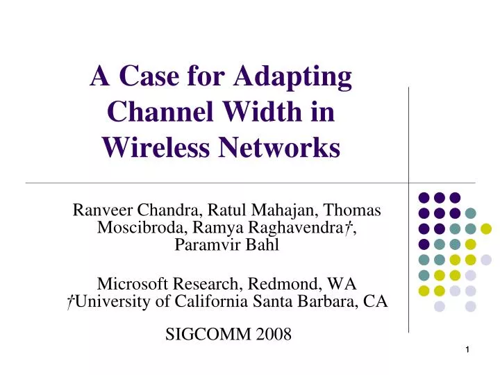
A Case for Adapting Channel Width in Wireless Networks. Ranveer Chandra, Ratul Mahajan, Thomas Moscibroda, Ramya Raghavendra † , Paramvir Bahl Microsoft Research, Redmond, WA † University of California Santa Barbara, CA SIGCOMM 2008. 1. 1. Outline. Introduction Changing Channel Width

E N D
A Case for Adapting Channel Width in Wireless Networks Ranveer Chandra, Ratul Mahajan, Thomas Moscibroda, Ramya Raghavendra†, Paramvir Bahl Microsoft Research, Redmond, WA †University of California Santa Barbara, CA SIGCOMM 2008 1 1
Outline • Introduction • Changing Channel Width • Impact of Channel Width • Benefits of Adapting Width • The Sample Width Algorithm • Performance Evaluation • Width Interoperability • Conclusions 2 2
Fundamental Variable - Channel Width (1) • Most wireless communication today involves the use of channels with preset widths • In 802.11 (Wi-Fi) b/g, the spectrum block is divided into 11 overlapping channels that are 20 MHz each and are separated by 5 MHz • In this paper, we argue that nodes in Wi-Fi networks should adapt the width of the communication channel based on their current needs and environmental conditions
Fundamental Variable - Channel Width (2) • To our knowledge, such adaptation has not been proposed or explored before • We find it surprising that Wi-Fi nodes dynamically change many variables today to improve communication except one of the most fundamental variable — the channel width • We make our case in three steps • Using measurements from controlled and live environments, we study properties of different channel widths • We identify several unique benefits of dynamically changing channel width that are otherwise not available today • Realizing these benefits requires practical channel width adaptation algorithms; in the third step, we show that this task is feasible at least in certain settings
Methodology (1) • The channel width of a wireless card is determined by the frequency synthesizer in the Radio Frequency (RF) front end circuitry • In most wireless systems, the frequency synthesizer is implemented using a Phase Locked Loop (PLL) • The reference clock frequency used by the PLL determines the channel width • We varied the channel width by changing the frequency of the reference clock that drives the PLL • We implemented this technique on off-the-shelf Atheros-based NICs • We changed the register values to generate signals on four channel widths of 5, 10, 20, and 40 MHz
Methodology (2) • We note that most Wi-Fi chipset designs, including Atheros, use a common reference clock for the RF transceiver and the baseband/MAC processor • The baseband/MAC processor uses the reference clock to control access to the wireless network • Therefore, slowing or increasing the clock rate affects 802.11 timing parameters • To ensure fair contention among flows on various channel widths, we modified the 802.11 slot time to be the same (20 μs) across all channel widths
Impact of Channel Widths • We characterize the impact of channel widths on three of the key metrics of wireless communication • flow throughput, packet reception range, and power consumption • Setup • For our experiments, we use two kinds of Atheros cards • We performed experiments in a controlled emulator setup and in an indoor office environment • We used CMU’s wireless channel emulator, which has two laptops connected through an FPGA • The FPGA implements the digital signal processing (DSP) routines that model signal propagation effects • such as small scale fading and signal attenuation
Peak Throughput (1) • We measure peak throughput using the emulator to minimize the impact of external interference • In these experiments the signal is attenuated by only 20 dB • As expected, the throughput increases as the channel width or the modulation rate is increased
Peak Throughput (2) • According to Shannon’s capacity formula the theoretical capacity of a communication channel is proportional to the channel width • Our measurements follow this relationship approximately but not exactly • For instance, at modulation 24, for 5 and 10 MHz the throughput is 4.04 and 7.65 respectively, which represents a factor of 1.89 • This less-than-doubling behavior is due to overheadsin the 802.11 MAC • Since some of these overheads are fixed in terms of absolute time • e.g., the slot-time is 20 μs, their relative overhead for wider channels is higher
Modeling Throughput (1) • We use the time tpacketrequired forone single packet transaction to derive the expected peak throughput • The basic timing parameters in ad hoc mode are tSIFS= 10 μs, tslot= 20 μs, and tDIFS= 2tslot+ tSIFS= 50 μs • At modulation-R, 4*R data bits are encoded per symbol • The transmission time for each symbol is tsymb= 4 μs • The data symbols are wrapped by a 20 μs preamble (synchronization and PLCP header) and a 6 μs signal extension • Let B be the channel width, and let β= 20MHz/B be a scaling ratio
Modeling Throughput (2) • In our setup, data and ACK size are sdata= 1536 bytes and sack= 14 bytes including all headers • Rackis the rate at which the MAC-layer ACK packet is transmitted. In our setup • Rack= 6 if R = 6, 9, 12, • Rack= 12 if R = 18, 24, • Rack= 24 if R ≥ 36
Transmission Range • Changing the channel width impacts the transmission range of a wireless signal • This is primarily because of two main reasons • improved SNR • resilience to delay • Improved SNR • We define the range threshold at which the loss rate is less than 10% • This threshold is 74 dB for 40 MHz and 81 dB for 5 MHz
Improved SNR (1) • The longer range of narrower widths can be explained as follows • For the same total energy used by aWi-Fi radio to transmit a signal, the transmission power depends on the channel width measured in Hz, and power per unit Hz • At narrower widths, the radio can transmit with higher power per unit Hz without changing the total transmission power 6 dB
Improved SNR (2) • In this experiment, we use an office as unit of distance and define range as the minimum number of offices crossed at which the loss rate between two nodes is 100% • An increase of X in range corresponds to an increase of X2 in area covered • Range increases can have significant practical impact for network coverage
Resilience to Delay (1) • At long communication distances, wireless receivers get multiple copies of a signal due to multipath reflections • Delay spread is the time difference between the arrival of the first and last copies of the multipath components • OFDM specifies a guard intervalat the start of every symbol to counter delay spread • For better packet recovery, a copy of the tail of the packet is included in the guard interval, called the cyclic prefix • For 802.11 at 20 MHz channel width, the guard interval is 800 ns, which is one-quarter of the symbol duration • This value of the guard interval has been shown to tolerate root-mean-square (r.m.s.) delay spreads of upto 250 ns [7] • However, the delay spreads are larger in outdoor environments, even up to 1 μs
Resilience to Delay (2) • The guard interval increases by a factor of two each time the channel width is halved • We expect higher delay spread resilience in narrower channel widths
Energy Consumption • We connect a 0.1 ohm resistor in series with the wireless card, and measure the current drawn through the resistor • We compute the power consumed by multiplying the current drawn through the resistor with the voltage supply of the wireless card (5V) • The decrease in power consumption can be explained by a slower clock speed that is used at narrower channel widths • In other areas of computing, energy optimization using clock frequency scaling of CPUs has of course been investigated for a long time
Results Summary • At small communication distances, throughput increases with channel width • The increase in not proportional to the channel width due to MAC layer overheads • Decreasing the channel width increases communication range • We get a 3 dB improvement by halving the channel width due to better SNR • Narrower channel widths also have better resilience to delay spread • Narrower channel widths consume less battery power when sending and receiving packets, as well as in the idle states • A 5 MHz channel width consumes 40% less power when idle, and 20% less power when sending packets than 40 MHz channel width
Benefits of Adapting Width • Reduce power and increase range simultaneously • Fixed channel width systems face a tough choice between increasing range and reducing power consumption • Adaptive channel width systems can have both • Narrower channels have both lower power consumption andlonger range • Reducing channel width may come at the cost of reduced throughput • but in some cases, narrowerchannels can improve throughput as well
Improving Flow Throughput • The key motivation for our work is the following observation • Although the peak throughput of wider channels is higher, the channel width offering the best throughput in a given setting depends on the “distance” between the nodes
Improving Fairness and Balancing Load in WLANs 40M 40M 10M 20M 10M 20M 20M
Improving Network Capacity • In this experiment, we use two sender-receiver pairs • All four laptops were in communication range of each other • “Near-Near” • when both senders are within 3 offices of their receivers • “Medium-near” • when one sender is 4 or 5 offices away from its receiver, and the other sender is within 3 offices • “Far-near” • one sender is more than 5 offices from its receiver, while the other is within 3 offices
The SampleWidth Algorithm (1) • Consider two nodes, Nsand Nr • They have k different channel widths B1, . . . , Bk • The goal of the algorithm is to select a channel width for a given objective • Maximizing throughput from Nsto Nr • Minimizing the energy consumption of Ns • At any given width, to maximize throughput, the nodes must use the best possible rate • SampleWidth uses a state-of-the-art autorate algorithm to find an efficient data rate on a specific width • If two nodes switch to a wider channel on which they are no longer within each other’s range, they will disconnect and the subsequent reconnection may require significant time • To keep the cost of sampling low, SampleWidth is based on sampling only adjacent widths
The SampleWidth Algorithm (2) • The decision to sample another width is based on the data rate, while throughput decides which channel width to use • Low throughput can be caused by either poor link quality that causes many losses or high contention that creates fewer opportunities for transmitting
Optimizing for Energy • In order to minimize the power consumption of the sender, we only change the decision rule in Line 15 • Instead of switching to the channel with highest throughput, we switch to the channel that is most energy-efficient • We use EPJiinstead of Tito compare across different channel widths • where EPJiis the bits per Joule for channel width Bi
Implementation • Our implementation of SampleWidth is spread across user and kernel space as a daemon and a modified driver • The nodes send beacons periodically, containing information about their adaptation capability, and to advertise themselves to other nodes • We implement a simple handshake protocol for coordination between nodes • A node that wishes to change its channel width sends a request packet to the other node, and waits for an acknowledgement before switching the channel width • A node that receives a request packet switches the channel width right after sending the acknowledgement • If after changing the channel width, two nodes do not receive beacons for more than two seconds, they switch to the narrowestchannel width and resume communication
Choosing the Correct Channel Width • A simple experiment in an indoor setting with a UDP transfer between two laptops • The receiver is positioned in a fixed location and the sender moves along a fixed trajectory at roughly constant speed
Reducing Power Consumption • In this experiment, each trial is one minute long and involves transferring a 20MB file 25 seconds into the experiment
Switching Overhead • The setup consists of two laptops • One laptop broadcasts packets at a high rate, and also periodically coordinates with the other laptop and switches channel width • We measured the time elapsed at the receiver between when the ACK was sent and the next broadcast packet was received • This time includes both the hardware switching time and the overhead of our coordination handshake R S R A B
Conclusions • We demonstrate for the first time how channel width of IEEE 802.11 based network communication channels can be changed adaptively in software • Our measurements show that this can lead to significant improvements • In range and connectivity, battery power-consumption, and capacity • Several hardware and software challenges must be met • On the hardware side, the most useful capability would be for radios to be able to decode packets at different widths • similar to decode different modulations - An initial header transmitted at a lowestwidth reveals the width of the remaining packet (switching overhead??) • On the software side, it requires new algorithms and models that are distinct from today’s graph-coloring based fixed width channel assignment models