Download
1 / 22
230 likes | 238 Views
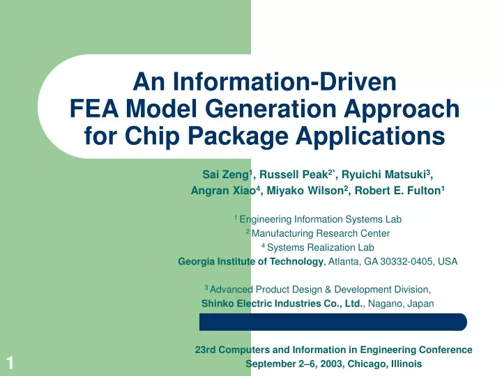
An Information-Driven FEA Model Generation Approach for Chip Package Applications. Sai Zeng 1 , Russell Peak 2* , Ryuichi Matsuki 3 , Angran Xiao 4 , Miyako Wilson 2 , Robert E. Fulton 1 1 Engineering Information Systems Lab 2 Manufacturing Research Center 4 Systems Realization Lab

E N D
An Information-Driven FEA Model Generation Approach for Chip Package Applications Sai Zeng1, Russell Peak2*, Ryuichi Matsuki3, Angran Xiao4, Miyako Wilson2, Robert E. Fulton1 1 Engineering Information Systems Lab 2 Manufacturing Research Center 4 Systems Realization Lab Georgia Institute of Technology, Atlanta, GA 30332-0405, USA 3 Advanced Product Design & Development Division, Shinko Electric Industries Co., Ltd., Nagano, Japan 23rd Computers and Information in Engineering Conference September 2–6, 2003, Chicago, Illinois
Example Chip Package ProductsSource: www.shinko.co.jp Quad Flat Packs (QFPs) Plastic Ball Grid Array (PBGA) Packages Wafer Level Package (WLP) Glass-to-Metal Seals System-in-Package (SIP)
Variable Topology Multi-Body (VTMB) FEA Meshing Challenges Idealized Analytical Bodies Decomposed FEA Geometry Models Meshing & Solving 1a 1b Design Model 1 2 2 1c 3a 3b 3c 3 original Labor-intensive “chopping” 1a 1b 1c 1 2 2 1d 1e 3 3a 3b topology change (no body change) 1a 1b 1 2 2 1c 3 3 1d 4 4a 4b 4c body change (includes topology change)
Traditional Approach • Small topology changes force mesh model rebuilding from scratch • Mesh models are barely reusable using traditional approach FEA Model Planning Sketches in Traditional Approach
Motivation • Competition in Chip Package Industry • Needs for new technologies and approaches facilitating seamless design and analysis integration • Difficulty in analysis model generation • Hundreds of components • Variable materials • Complex geometric shapes • Changeable connectivity configurations • Modifications resulting in tedious and time consuming FEA modeling process • package design • analysis discipline • idealization
Objective • Integrate chip package design using Finite Element Analysis • Automate the FEA modeling process to save the modeling time and reduce the human errors • Increase reusability of the mesh models during chip package modification and redesign
Frame of Reference – Multi-Representation Architecture (MRA)for CAD-CAE Interoperability • Composed of four representations (information models) • Provides flexible, modular mapping between design & analysis models • Creates automated, product-specific analysis modules (CBAMs) • Represents design-analysis associativity explicitly
Ψ Ψ T T body body ABB RMM RMM SMM 0 0 1 1 body body body body 4 4 3 3 body body 2 2 ABB Model RMM Model SMM Model Information-Driven FEA Modeling Approach • Mapping process ABBΨRMM transforms the ABB model into a ready-to-mesh model (RMM) by geometry decomposition. • Mapping process RMMΨSMM transforms the RMM into the solvable FEA-based SMM in an automated manner. • ABB captures analytical concepts • FEA based SMM = object wrapper • Integrates pre-processor, solver and post processor information • Includes vendor-specific script file format Information-Driven FEA Modeling Approach
Analysis Building Block Models (ABBs) • An ABB model represents engineering analytical concepts as a set of computable information entities • Independent from specific solution techniques • Analysis knowledge is captured by employing object-orient information representation technology Information Content for Example ABB Concepts
Analysis Building Block Models (ABBs) • A diving board example is presented to illustrate an ABB system A Graphical View of an ABB System and its Analytical Bodies and Connectivity
Ready-to-Mesh Models (RMMs) • A RMM is obtained by geometric decomposition from a corresponding ABB • The geometry of a RMM model is composed of geometry pieces that are convex-shaped and meshable using efficient and cheap meshing techniques. • Building blocks of an ABB can be reused to construct a RMM • Associativity of building blocks is changed before and after decomposition A Graphical View of an RMM System and its Decomposed Bodies and Connectivity
Decomposition Architecture • Decomposition is implemented to obtain conformal mesh along the interfaces of connected bodies • Decomposition deals with geometry exclusively • Decomposed model consists of decomposed bodies connected along equivalent faces Decomposition Process
Decomposition Associativity Mechanism • An mechanism is required to keep track of the information associativity during the geometry decomposition Compositional Relations for Boundary Condition Building Blocks and Continuum Building Blocks after Decomposition
Solution Method Model (SMM) • It is an information entity that wraps solution tool inputs and outputs into a single logical package • SMM includes the SMM information objects and the SMM tool agent
RMM Model ABB - SMM- Solution Tool Interaction • ABB systems generate SMMs based on solution method considerations • Via RMMs in these problem types • Solution tool capabilities are also usually considered
A Chip Package Thermomechanical Analysis Case – An ABB system • Four linear elastic thermomechanical continua • Continua are glued together • One rigid pin support • Uniform temperature drop as thermal load
A Chip Package Thermomechanical Analysis Case – An RMM • A RMM is obtained after automatic decomposition of a ABB system • With composition mechanism, information associated with geometry can be assigned on the corresponding decomposed geometry • This model can be directly input into the SMM to generate a conformal FEA meshed model
A Chip Package Thermomechanical Analysis Case – An SMM • The tool agent translates the model information into the tool-specific computable formats, e.g. a PATRAN command language ASCII file • Modeling time is counted as information instance object creation time • Modeling time is dramatically reduced comparing to traditional FEA modeling approach
Complex Chip Package Thermomechanical Analysis Case Decomposition ABB Model consisting 182 Input bodies RMM consisting 9056 Decomposed bodies FEA SMM
Closure • Presentation of information-driven FEA modeling approach • Demonstration representing product-independent analysis concepts as knowledge-based objects: • semantically rich • reusable • modular and tool-independent • Reduction of FEA modeling time (variable topology multi-body application) - reduced from days/hours to hours/minutes • Enhancement of knowledge capture and automation level vs. traditional direct FEA modeling approaches
Acknowledgements We are particularly grateful for the support of the following people: • Kuniyuki Tanaka, Yukiharu Takeuchi, and Shinichi Wakabayashi of Shinko Electric Ltd. • Greg Bettencourt of Shinko Electric America, Inc. • Rod Dreisbach of The Boeing Company • Mike Dickerson of the NASA Jet Propulsion Lab (JPL) • Manas Bajaj, Greg M. Mocko, Edward J. Kim, Injoong Kim at the Engineering Information Systems Lab, Georgia Tech