Download
1 / 44
440 likes | 505 Views
TWO-DIMENSIONAL SIMULATIONS OF COHERENT FLUCTUATION-DRIVE TRANSPORT IN A HALL THRUSER. Cheryl M. Lam and Mark A. Cappelli Stanford Plasma Physics Laboratory Stanford University, Mechanical Engineering Department Eduardo Fernandez Eckerd College, Department of Mathematics and Physics

E N D
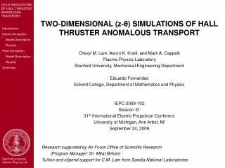
TWO-DIMENSIONAL SIMULATIONS OF COHERENT FLUCTUATION-DRIVE TRANSPORT IN A HALL THRUSER Cheryl M. Lam and Mark A. Cappelli Stanford Plasma Physics Laboratory Stanford University, Mechanical Engineering Department Eduardo Fernandez Eckerd College, Department of Mathematics and Physics 33rd International Electric Propulsion Conference Washington, DC October 6-10, 2013
Hall Thruster • Electric (space) propulsion device • Demonstrated high thrust efficiencies • Up to 60% (depending on operating power) • Deployed production technology • Design Improvements • Better physics understanding • Basic Premise: Accelerate heavy (positive) ions through electric potential to create thrust • E x B azimuthal Hall current • Radial B field (r) • Axial E field (z) • Ionization zone (high electron density region) • Electrons “trapped” • Neutral propellant (e.g., Xe) ionized via collisions with electrons Plasma • Ions accelerated across imposed axial potential (Ez / Φz) & ejected from thruster
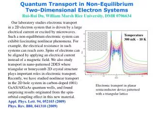
Motivation • Anomalous electron transport • Super-classical electron mobility observed in experiments1 • Theory: Correlated fluctuations in ne and uez induce super-classical electron transport • Renewed interest in rotating spoke (near anode) 1Meezan, N. B., Hargus, W.A., Jr., and Cappelli, M. A., Physical Review, Vol. 63, No. 2, 026410, 2001.
Motivation Moderate “Low” Frequency Mode (~700 kHz) *A. Knoll, Ph.D. Thesis, Stanford University, 2010
Anode Cathode Anode Exit Plane 2D (z-θ) Simulation Channel Diameter = 9 cm Channel Length = 8 cm • First fully-resolved 2D z-θ simulations of entire thruster2 • Predict azimuthal (E x B) fluctuations • Hybrid Fluid-PIC • Ions: Non-magnetized particles • Neutrals: Particles (Injected at anode; Local ionization rate) • Electrons: 2D Fluid • Continuity (Species & Current) • 2D Momentum: Drift-Diffusion • 1D Energy (in z) G 0 extends 4 cm past channel exit z: 40 points, non-uniform θ: 50 points, uniform ni = neQuasineutrality 2Lam, C. M., Knoll, A. K., Cappelli, M. A., and Fernandez E., IEPC-2009-102.
Electron Fluid Equations Classical Mobility • Momentum: Drift-Diffusion • Neglect inertial terms • Correlated azimuthal fluctuations induce axial transport: Classical Diffusion E x B classical diamagnetic classical E x B diamagnetic Previous models under-predict Jez=qneuez θ fluctuations/dynamics
where Electron Fluid Equations • Combine current continuity and electron - momentum to get convection-diffusion equation for Φ: • Energy (Temperature) Equation • 1D in z (φ is electric potential)
LEAP FROG Time Advance Particle Positions & Velocities Neutrals & Ions (subject to F=qE) EGRID EPART Ionize Neutrals Inject Neutrals Calculate Plasma Properties ni-PART, vi-PART, nn-PART, vn-PART ni-GRID, vi-GRID, nn-GRID, vn-GRID QUASINEUTRALITY: ne = ni = nplamsa Spline RK4 Time Advance Te=Te(ne, ve) DIRECT SOLVE 2nd-order F-D Iterative Solve Φ Calculate Φ=Φ(ne, vi-GRID) ↔ EGRID Calculate ve=ve(Φ, ne, Te) r < ε0 CONVERGED r = Φ – Φlast-iteration Calculate vi-GRID-TEST= vi-GRID(EGRID) Solution Algorithm Boundary Conditions: • Dirichlet in z (Φ,Te) • Periodic in θ
Recent Progress & Challenges • Addition of particle collisions with thruster walls • Neutral particles reflected upon collision with anode or inner/outer radial channel walls • Ions recombine (with donor electron) to form neutral upon collision with inner/outer radial channel walls • Particles still otherwise collisionless, i.e., we do not model particle-particle collisions • Finer axial (z) grid resolution near anode • Stability challenges • Sensitivity to Initial Conditions and Boundary Conditions • Strong fluctuation in Te • Current conservation • Finite Difference – present model • Finite Volume
40 points non-uniform in z 50 points uniform in θ Previous 100V (IEPC 2009) 160V simulation (new) 61 points uniform in z 25 points uniform in θ 100V simulation (new) Numerical Grid
Plasma Density Electron Temperature Axial Ion Velocity Electric Potential Time-Averaged Plasma Properties
E x B Fluctuations Axial Electron Velocity Distinct wave behavior observed: • Near exit plane (as before) • Tilted: + z, - ExB • Higher frequency, faster moving, shorter wavelength • Transition to standing wave (purely +z) downstream of exit plane (z = 0.1 m) • Mid-channel • Tilted: - z, + E x B • Lower frequency, slow moving, longer wavelength • “More tilted” (stronger/faster θ component) – compared to previous • Near anode • Rotating spoke • m = 2 (100V)
Anode Cathode E x B Rotating Spoke • Near anode (z ≤ 0.01 m) • Primarily azimuthal • m = 2 • vph = ~ 1 km/s • f = 10-20 kHz
Correlated ne and uez fluctuations generate axial electron current Uncorrelated Correlated fluctuations generate axial current
Discharge current is low and decreases with timeExperiment: ~2 A (for 100V)
Discharge current is low and decreases with timeExperiment: ~2 A (for 100V)
Electron Transport Axial Electron Mobility:
Electron Transport • Preliminary Simulation: Spoke does not lead to anomalous transport Axial Electron Mobility:
160V SimulationElectron Transport Spoke does not lead to anomalous transport Axial Electron Mobility:
Summary • Rotating spoke observed • First simulations to predict spoke: important to resolve full azimuth • Model: added particle wall collisions (neutral reflection, ion recombination) • Consistent with theory and experimental observations • Preliminary simulations: Spoke generates current, but does NOT lead to anomalous transport. • Remaining challlenges • Low voltage (100V) case: plasma cooling/quenching? • Stability: Te instability, ICs, BCs • Current conservation Finite Volume discretization
Rotating Spoke • Near anode (z ≤ 0.01 m) • Primarily azimuthal • m = 2 • vph = ~ 1 km/s • f = 10-20 kHz
Motivation Thruster Life/Erosion Simulations* • Develop predictive lifetime/erosion in Hall thrusters Computed erosion behavior over 2500 hours: Plasma properties are evolved over the life of the thruster Erosion rate on the inner wall Erosion rate on the outer wall Ion density in the Hall thruster simulation domain r - z *E. Sommier, M. K. Scharfe, N. Gascon, M. A. Cappelli, and E. Fernandez, IEEEITransactions on Plasma Science, 35 (5), October 2007, pp. 1379-1387.
ξ t Azimuthal Fluctuations induce Axial Transport Eθ= E0cos(ωt) ne = n0cos(ωt + ξ) Consider Induced Current Induced current depends on phase shift ξ
Erosion rate on the inner wall Erosion rate on the outer wall Motivation • Primary Design Concern: Thruster Lifetime • Wall (ceramic insulator) erosion • Typical Lifetime: ~1000 hours (mpropellant≈ msystem) • Predictive Modeling & Simulation for Design Optimization Design Objective: Keep (fast) ions from hitting walls • Thruster geometry & operating voltage: fixed • Design parameter: B field (shape & strength) • Imposed B-field ↔ Ez • Underlying plasma physics • Electron transport • Plasma density & E field fluctuations • Ionization (via collisions) • Plasma-surface interactions (e.g., sputtering, electron damping, recombination at walls) • Certain physical phenomena observed in experiment not well understood Numerical experiments • Research focus: Azimuthal (θ) dynamics Axial (z) electron transport ** Movie courtesy of E. Sommier
Motivation • Hall thruster anomalous electron transport • Super-classical electron mobility observed in experiments1 • Correlated (azimuthal) fluctuations in ne and ue • 2D r-z models use tuned mobility to account for azimuthal effects2,3 • 3D model is computationally expensive • First fully-resolved 2D z-θ simulations of entire thruster ** Initial development by E. Fernandez • Predict azimuthal (ExB) fluctuations • Inform r-z model • Motivate 3D model Channel Diameter = 9 cm Channel Length = 8 cm 1Meezan, N. B., Hargus, W.A., Jr., and Cappelli, M. A., Physical Review, Vol. 63, No. 2, 026410, 2001. 2Fife, J. M., Ph.D. Dissertation, Massachusetts Inst. of Technology, Cambridge, MA, 1999. 3Fernandez et al, “2D simulations of Hall thrusters,” CTR Annual Research Briefs, Stanford Univ.,1998.
Hybrid Fluid-PIC Model • Ions: Collisionless particles (Particle-In-Cell approach) • Non-magnetized • Wall collisions not modeled • Neutrals: Collisionless particles (Particle-In-Cell approach) • Injected at anode per mass flow rate • Half-Maxwellian velocity distribution based on r-z simulation (w/ wall effects) • Ionized per local ionization rate • Based on fits to experimentally-measured collision cross-sections, assuming Maxwellian distribution for electrons • Electrons: Fluid • Continuity (species & current) • Momentum • Drift-diffusion equation • Inertial terms neglected • Energy (1D in z) • Convective & diffusive fluxes • Joule heating, Ionization losses, Effective wall loss Quasineutrality: ni = ne
Channel Diameter = 9 cm Channel Length = 8 cm Anode Cathode Anode Exit Plane extends 4 cm past channel exit z: 40 points, non-uniform θ: 50 points, uniform Geometry • 2D in z-θ • No radial dynamics • E x B + θ • Br: purely radial (measured from SHT) • Imposed operating (based on operating condition) G
Interpolation: Particle Grid rNW rNE FNW FNE rSE FSE rSW FSW Interpolation: Grid Particle PIC Ions & Neutrals • Particle-In-Cell (PIC) Approach • Particles: arbitrary positions • Force Particle acceleration Interpolate: Grid Particle • Plasma properties evaluated at grid points (Coupled to electron fluid solution) • Interpolate: Particle Grid • Bilinear Interpolation • Ions subject to electric force: ≈ 0 neglect
Electron Fluid Equations • Species Continuity • Current Continuity 0 ni = ne
Electron Fluid Equations • Momentum: Drift-Diffusion • Neglect inertial terms Previous models under-predict Jez=qneuez θ fluctuations/dynamics Classical Mobility
Electron Fluid Equations • Momentum: Drift-Diffusion • Neglect inertial terms • Correlated azimuthal fluctuations induce axial transport: Previous models under-predict Jez=qneuez θ fluctuations/dynamics
Unlike fully PIC codes, the electric potential is not obtained from a Poisson equation:
E x B Anode Cathode E x B E x B Fluctuations in θ f = 40 KHz λθ = 5 cm vph = 4000 m/s f = 700 KHz λθ = 4 cm vph = 40,000 m/s
Streak Plots E x B E x B
Future Work • Numerical Stability • Alternative solution algorithms • Timestep and grid refinement • Governing physics • Enhanced electron mobility • Wall model • Potential BC • Power supply circuit model • Recombination • Magnetized ions • Model validation against experiments