Download
1 / 44
460 likes | 684 Views
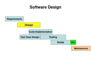
Software Design. Static Modeling using the Unified Modeling Language (UML). Material based on [Booch99, Rambaugh99, Jacobson99, Fowler97, Brown99]. Chapter 2, Modeling with UML. Overview: modeling with UML. What is modeling? What is UML? Use case diagrams Class diagrams

E N D
Software Design Static Modeling using theUnified Modeling Language (UML) Material based on [Booch99, Rambaugh99, Jacobson99, Fowler97, Brown99] Software Design (UML)
Overview: modeling with UML • What is modeling? • What is UML? • Use case diagrams • Class diagrams • Sequence diagrams • Activity diagrams
What is modeling? • Modeling consists of building an abstraction of reality. • Abstractions are simplifications because: • They ignore irrelevant details and • They only represent the relevant details. • What is relevant or irrelevant depends on the purpose of the model.
Why model software? Why model software? • Software is getting increasingly more complex • Windows XP > 40 million lines of code • A single programmer cannot manage this amount of code in its entirety. • Code is not easily understandable by developers who did not write it • We need simpler representations for complex systems • Modeling is a mean for dealing with complexity
What is UML? • UML (Unified Modeling Language) • An emerging standard for modeling object-oriented software. • Resulted from the convergence of notations from three leading object-oriented methods: • OMT (James Rumbaugh) Object Modeling Technique • OOSE (Ivar Jacobson) Object Oriented Software Engineering • Booch (Grady Booch) • Reference: “The Unified Modeling Language User Guide”, Addison Wesley, 1999. • Supported by several CASE tools • Rational ROSE • TogetherJ
UML: First Pass • You can model 80% of most problems by using about 20 % UML • We teach you those 20%
UML First Pass • Use case Diagrams • Describe the functional behavior of the system as seen by the user. • Class diagrams • Describe the static structure of the system: Objects, Attributes, Associations • Sequence diagrams • Describe the dynamic behavior between actors and the system and between objects of the system • Statechart diagrams • Describe the dynamic behavior of an individual object (essentially a finite state automaton) • Activity Diagrams • Model the dynamic behavior of a system, in particular the workflow (essentially a flowchart)
Watch ReadTime SetTime WatchUser WatchRepairPerson ChangeBattery UML first pass: Use case diagrams Use case Package Actor Use case diagrams represent the functionality of the system from user’s point of view
1 1 1 1 LCDDisplay Time now blinkIdx blinkSeconds() blinkMinutes() blinkHours() stopBlinking() referesh() UML first pass: Class diagrams Class diagrams represent the structure of the system Association Class Multiplicity Watch 1 2 PushButton state push()release() Attribute Operations
:Watch :LCDDisplay :Time :WatchUser pressButton1(& 2) blinkHours() pressButton1() blinkMinutes() pressButton2() incrementMinutes() refresh() pressButtons1And2() commitNewTime() stopBlinking() UML first pass: Sequence diagram Actor Object Message Activation Lifeline Sequence diagrams represent the behavior as interactions
UML first pass: Statechart diagrams for objects with interesting dynamic behavior State Event Initial state Transition Final state Represent behavior as states and transitions
Used during requirements elicitation to represent external behavior Actors represent roles, that is, a type of user of the system Use cases represent a sequence of interaction for a type of functionality The use case model is the set of all use cases. It is a complete description of the functionality of the system and its environment Passenger PurchaseTicket Use Case Diagrams
An actor models an external entity which communicates with the system: User External system Physical environment An actor has a unique name and an optional description. Examples: Passenger: A person in the train GPS satellite: Provides the system with GPS coordinates Passenger Actors
A use case represents a class of functionality provided by the system as an event flow. A use case consists of: Unique name Participating actors Entry conditions Flow of events Exit conditions Special requirements PurchaseTicket Use Case
Name:Purchase ticket Participating actor:Passenger Entry condition: Passenger standing in front of ticket distributor. Passenger has sufficient money to purchase ticket. Exit condition: Passenger has ticket. Event flow: 1. Passenger selects the number of zones to be traveled. 2. Distributor displays the amount due. 3. Passenger inserts money, of at least the amount due. 4. Distributor returns change. 5. Distributor issues ticket. Use Case Diagram: Example Anythingmissing? Exceptional cases!
<<extends>> relationships represent exceptional or seldom invoked cases. The exceptional event flows are factored out of the main event flow for clarity. Use cases representing exceptional flows can extend more than one use case. The direction of a <<extends>> relationship is to the extended use case Passenger PurchaseTicket <<extends>> OutOfOrder TimeOut <<extends>> <<extends>> <<extends>> Cancel NoChange The <<extends>> Relationship
<<includes>> relationship represents behavior that is factored out of the use case. <<includes>> behavior is factored out for reuse, not because it is an exception. The direction of a <<includes>> relationship is to the using use case (unlike <<extends>> relationships). Passenger PurchaseMultiCard PurchaseSingleTicket <<includes>> <<includes>> NoChange Cancel CollectMoney <<extends>> <<extends>> The <<includes>> Relationship
Use Case Diagrams: Summary • Use case diagrams represent external behavior • Use case diagrams are useful as an index into the use cases • Use case descriptions provide meat of model, not the use case diagrams. • All use cases need to be described for the model to be useful.
Person name : String address : Address birthdate : Date ssn : Id eat sleep work play Class Operations The name of the class is the only required tag in the graphical representation of a class. It always appears in the top-most compartment. Class Name Class Attributes An attribute is a named property of a class that describes the object being modeled.In the class diagram, attributes appear in the second compartment just below the name-compartment. Class Operations Operations describe the class behavior and appear in the third compartment. Software Design (UML)
Relationships • In UML, object interconnections (logical or physical), are • modeled as relationships. • There are three kinds of relationships in UML: • dependencies • generalizations • associations Software Design (UML)
Dependency Relationships A dependency indicates a semantic relationship between two or more elements. The dependency from CourseSchedule to Course exists because Course is used in both the add and remove operations of CourseSchedule. CourseSchedule Course add(c : Course) remove(c : Course) Software Design (UML)
Generalization Relationships Person A generalization connects a subclass to its superclass. It denotes an inheritance of attributes and behavior from the superclass to the subclass and indicates a specialization in the subclass of the more general superclass. Student Software Design (UML)
Generalization Relationships (Cont’d) UML permits a class to inherit from multiple superclasses, although some programming languages (e.g., Java) do not permit multiple inheritance. Student Employee TeachingAssistant Software Design (UML)
Association Relationships If two classes in a model need to communicate with each other, there must be link between them. An association denotes that link. Student Instructor Software Design (UML)
Association Relationships (Cont’d) We can indicate the multiplicity of an association by adding multiplicity adornments to the line denoting the association. The example indicates that a Student has one or more Instructors: Student Instructor 1..* Software Design (UML)
Association Relationships (Cont’d) The example indicates that every Instructor has one or more Students: Student Instructor 1..* Software Design (UML)
Association Relationships (Cont’d) We can also indicate the behavior of an object in an association (i.e., the role of an object) using rolenames. teaches learns from Student Instructor 1..* 1..* Software Design (UML)
Association Relationships (Cont’d) We can also name the association. membership Student Team 1..* 1..* Software Design (UML)
Association Relationships (Cont’d) We can specify dual associations. member of Student Team 1..* 1..* 1 president of 1..* Software Design (UML)
Association Relationships (Cont’d) We can constrain the association relationship by defining the navigability of the association. Here, a Router object requests services from a DNS object by sending messages to (invoking the operations of) the server. The direction of the association indicates that the server has no knowledge of the Router. Router DomainNameServer Software Design (UML)
next LinkedListNode previous Association Relationships (Cont’d) A class can have a self association. Software Design (UML)
Car Engine Transmission Association Relationships (Cont’d) We can model objects that contain other objects by way of special associations called aggregations and compositions. An aggregation specifies a whole-part relationship between an aggregate (a whole) and a constituent part, where the part can exist independently from the aggregate. Aggregations are denoted by a hollow-diamond adornment on the association. Software Design (UML)
Scrollbar Titlebar Menu Association Relationships (Cont’d) A composition indicates a strong ownership and coincident lifetime of parts by the whole (i.e., they live and die as a whole). Compositions are denoted by a filled-diamond adornment on the association. Window 1 1 1 1 1 1 .. * Software Design (UML)
Software Design Dynamic Modeling using the Unified Modeling Language (UML) Software Design (UML)
State Machine An object must be in some specific state at any given time during its lifecycle. An object transitions from one state to another as the result of some event that affects it. You may create a state diagram for any class, collaboration, operation, or use case in a UML model . There can be only one start state in a state diagram, but there may be many intermediate and final states. Software Design (UML)
start state simple state final state concurrent composite state sequential composite state State Machine Software Design (UML)
download course offerings downloading unscheduled make a course selection selecting verify selection make a different selection verifying select another course check schedule sign schedule checking schedule scheduled State Machine Software Design (UML)
Collaboration Diagram A collaboration diagram emphasizes the relationship of the objects that participate in an interaction. Unlike a sequence diagram, you don’t have to show the lifeline of an object explicitly in a collaboration diagram. The sequence of events are indicated by sequence numbers preceding messages. Object identifiers are of the form objectName : className, and either the objectName or the className can be omitted, and the placement of the colon indicates either an objectName: , or a :className. Software Design (UML)
: Order Entry Window Object Sequence Number 1: prepare() Message : Order Self-Delegation 5: needToReorder() 3: check() 2*: prepare() 4: [check == true] remove() : Order Line : Stock Item 7: [check == true] new 6: new :Delivery Item :Reorder Item [Fowler,97] Collaboration Diagram Software Design (UML)
Activity Diagram An activity diagram is essentially a flowchart, showing the flow of control from activity to activity. Use activity diagrams to specify, construct, and document the dynamics of a society of objects, or to model the flow of control of an operation. Whereas interaction diagrams emphasize the flow of control from object to object, activity diagrams emphasize the flow of control from activity to activity. An activity is an ongoing non-atomic execution within a state machine. - The UML User Guide, [Booch,99] Software Design (UML)
Receive Order Multiple Trigger for each line * item on order Check Cancel Authorize Line Order Payment [failed] Item [succeeded] [in stock] Assign to Order Synchronization Condition [need to [stock assigned to reorder] Reorder all line items and Item payment authorized] Dispatch Order [Fowler,97] Software Design (UML)
References [Booch99] Booch, Grady, James Rumbaugh, Ivar Jacobson, The Unified Modeling Language User Guide, Addison Wesley, 1999 [Rambaugh99] Rumbaugh, James, Ivar Jacobson, Grady Booch, The Unified Modeling Language Reference Manual, Addison Wesley, 1999 [Jacobson99] Jacobson, Ivar, Grady Booch, James Rumbaugh, The Unified Software Development Process, Addison Wesley, 1999 [Fowler, 1997] Fowler, Martin, Kendall Scott, UML Distilled (Applying the Standard Object Modeling Language), Addison Wesley, 1997. [Brown99] First draft of these slides were created by James Brown. Software Design (UML)