Download
1 / 68
680 likes | 873 Views
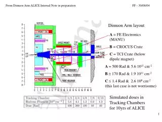
Low mass dimuon acceptance. Shiuan-Hal Shiu. Contents. Introduction The result of varying M1 current The result of varying M2 current Dump/Target separation Conclusion. The location of M1 and M2. Configuration file. Why varying the magnet current. Original. Want.

E N D
Low mass dimuon acceptance Shiuan-Hal Shiu
Contents • Introduction • The result of varying M1 current • The result of varying M2 current • Dump/Target separation • Conclusion
The location of M1 and M2 Configuration file
Why varying the magnet current Original Want
Why varying the magnet current In low mass region the dimuon events have small opening angle
Fix M2 current and vary M1 current • Use the E906 Fast Monte Carlo simulation for study configuration data. • The configuration file is “fe198v5.dat”. • By changing the entry “current and step to scale” we can adjust the M1 or M2 current. The input to the simulation is decided by Ykick*input/2000 and the tracking plane from #2 to #13 will affected by this factor.
The top diagram is the mass distribution of generated dimuon pairs. • The middle diagram is the mass distribution of accepted dimuon pairs. • The bottom diagram “Acceptance” as a function of dimuon mass.
The mass range of generated dimuon pairs is from 0.2Gev to 15Gev • Green line is the acceptance value with the original M1 current setting. • By increasing the current we find that the peak of acceptance is shifting to high mass end. • Reducing the M1 current can increase the acceptance in the low-mass region.
Fix M1 current and vary M2 current • Fix the M1 current, and change the M2 current (Ykick).
M2*1.5 M2*1 M2*0.5
M2*1.5 M2*1 M2*0.5
M2*1.5 M2*1 M2*0.5
Dump/Target separation M1*1 • Cuts conditions • Purple:all events • Green: xF>0 and • M>4.5 GeV • and pz>20 GeV • Blue: Green and • |ytrack|>2.25 in at z=0 (zdump) • Red: Blue and • |ytrack|<10.0 in at z=-60 (zstart) Target Dump
Dump/Target separation M1*1 M1*0.5 M1*0.1 Target retrace and dump retrace can be separated Target retrace and dump retrace can not be separated
Dump/Target separation M1*0.5 1 3 2 4
Dump/Target separation M1*0.1 1 3 2 4 Reducing the M1 current will lead the z resolution bad.
Change the target location The target original location is at -70 to -50. We change it to -150 to -130.
Change the target location M1*0.5 1 3 2 4
Change the target location M1*0.1 1 3 2 4 Changing target location can not improve the z resolution.
Cuts conditions • Purple:all events • Green: xF>0 and • M>4.5 GeV • and pz>20 GeV • Blue: Green and • |ytrack|>2.25 in at z=0 (zdump) • Red: Blue and • |ytrack|<10.0 in at z=-60 (zstart) • Moving the cut condition at zdump to Station 1 and change the value.
Original Changed
Changed Original • Try |ytrack|>8 in at z=238 (before station1)
M1*0.5 1 3 2 4
M1*0.1 1 3 2 4 Changing cut condition can not improve the z resolution.
Check the relations of retrace mass and retrace z • Left diagram is using the original cut condition. • The mass cut is “>4.5Gev” here. • After applied the cut(mass >4.5 Gev) , we can see that the events are almost spread in the region which less than z=0.
Check the relations of retrace mass and retrace z • Left diagram is using the original cut condition but mass cut is “<4.5Gev”. • After applied the cut , we can see that the events are still scattered throughout the x axis. M1*0.5 M1*0.1
Opening angle of muon pairs fe198v5m101 mrtr.le.4.5 zrtr.le.0 fe198v5m101 mrtr.le.4.5 zrtr.ge.0 fe198v5m101_dump mrtr.le.4.5 zrtr.le.0 fe198v5m101_dump mrtr.le.4.5 zrtr.ge.0
Opening angle of muon pairs fe198v5m101 mrtr.le.4.5 zrtr.le.0 fe198v5m101 mrtr.le.4.5 zrtr.ge.0 fe198v5m101_dump mrtr.le.4.5 zrtr.le.0 fe198v5m101_dump mrtr.le.4.5 zrtr.ge.0
Conclusion • Reducing the M1 current can increase the acceptance of low mass dimuons. • Adjusting the M2 current does not change the acceptance significantly. • Howerer, decreasing M2 current can enlarge the acceptance. • After reducing the M1 current, the z resolution is become bad. • Changing target location and cut condition can not improve the Dump/Target resolution. • Low mass events are affected by the multiple scattering seriously.