Download
1 / 26
280 likes | 309 Views
Learn about the Theory of Structures, Truss Analysis, and Virtual Work Methods for calculating deflections and displacements in structures. Understand the principles of work and energy and their application in structural engineering.

E N D
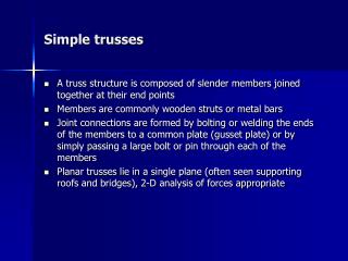
Deflection: Virtual Work Method; Trusses Theory of Structure - I
Contents • External Work and Strain Energy • Principle of Work and Energy • Principle of Virtual Work • Method of Virtual Work: • Trusses
F L P Eigen work Ue D x D F Eigen work External Work and Strain Energy Most energy methods are based on the conservation of energy principle, which states that the work done by all the external forces acting on a structure, Ue, is transformed into internal work or strain energy, Ui. Ue = Ui • External Work-Force. As the magnitude of F is gradually increased from zero to some limiting value F = P, the final elongation of the bar becomes D.
F ´ + P Eigen work P F Displacement work D D´ D´ x P D L L F´ (Ue)Total = (Eigen Work)P + (Eigen Work)F´ + (Displacement work) P
F 20 kN L L 1 cm x (m) 0.01 m 20 kN
20 kN Eigen work 15 kN F Displacement work 0.75 cm 0.0075 0.01 0.25 cm x (m) 15 kN L L L 0.75 cm 5 kN 15 kN
M ´ + M Eigen work M M Displacement work dq M q q´ q -----(8-12) Eigen work -----(8-13) -----(8-14) • External Work-Moment.
s e L D N • Strain Energy-Axial Force.
P s w M M dq x dx e dx L • Strain Energy-Bending
t T c g dq g J T • Strain Energy-Torsion dx For reference: Strength of Material by Singer, Fourth Edition, Page 67-68
t V V g dy g dx • Strain Energy-Shear For reference: Strength of Material by Singer, Fourth Edition, Page 161-163
P L M diagram P M -PL x V x SMx= 0: + Principle of Work and Energy
u L Virtual loadings Virtual loadings u A Real displacements Real displacements P´ = 1 Apply virtual load P´ first u L u A dL D P1 Then apply real load P1. Principle of Virtual Work 1 • D = Su • dL In a similar manner, 1 • q = Suq • dL
P1 n1 N1 P2 n6 N6 N4 n4 N2 n2 n3 N3 n5 N5 B B n7 n8 n9 N7 N8 N9 D 1kN Method of Virtual Work : Truss • External Loading. Where: 1 = external virtual unit load acting on the truss joint in the stated direction of D n = internal virtual normal force in a truss member caused by the external virtual unit load D = external joint displacement caused by the real load on the truss N = internal normal force in a truss member caused by the real loads L = length of a member A = cross-sectional area of a member E = modulus of elasticity of a member
Temperature Where: D = external joint displacement caused by the temperature change a = coefficient of thermal expansion of member DT = change in temperature of member • Fabrication Errors and Camber Where: D = external joint displacement caused by the fabrication errors DL = difference in length of the member from its intended size as caused by a fabrication error
C 4 kN 3 m A B 4 m 4 m Example 8-15 The cross-sectional area of each member of the truss shown in the figure is A = 400 mm2 and E = 200 GPa. (a) Determine the vertical displacement of joint C if a 4-kN force is applied to the truss at C. (b) If no loads act on the truss, what would be the vertical displacement of joint C if member AB were 5 mm too short? (c) If 4 kN force and fabrication error are both accounted, what would be the vertical displacement of joint C.
1 kN -2.5 +2.5 -0.833 -0.833 4 kN 2 0.667 0 0.5 kN 0.5 kN 1.5 kN C 1.5 kN 4 kN C A B B A n (kN) N(kN) SOLUTION Part (a) • Virtual Force n. Since the vertical displacement of joint C is to be determined, only a vertical 1 kN load is placed at joint C. The n force in each member is calculated using the method of joint. • Real Force N. The N force in each member is calculated using the method of joint.
1 kN C C 4 kN C B A B A A B n (kN) N (kN) L (m) = C B A nNL (kN2•m) DCv= 0.133 mm, -0.833 -0.833 -2.5 +2.5 0.667 2 5 5 8 -10.41 10.41 10.67
1 kN C -0.833 -0.833 A 0.667 B n (kN) 5 mm DCv= -3.33 mm, DCv= -3.20 mm, Part (b): The member AB were 5 mm too short Part (c): The 4 kN force and fabrication error are both accounted. DCv= 0.133 - 3.33 = -3.20 mm
F E 4 m D A B C 4 m 4 m 4 m 4 kN 4 kN Example 8-16 Determine the vertical displacement of joint C of the steel truss shown. The cross-section area of each member is A = 400 mm2 and E = 200 GPa.
F E F E -0.333 -4 4 m 4 m -5.66 -0.943 D D -0.471 0 A A -5.66 -0.471 1 0.333 4 4 B C B C 0 0 0.333 0.667 0.667 4 4 4 4 m 4 m 4 m 4 m 4 m 4 m n (kN) 4 kN 4 kN 0.333 kN 0.667 kN 4 kN 4 kN N(kN) 1 kN SOLUTION • Virtual Force n. Since the vertical displacement of joint C is to be determined, only a vertical 1 kN load is placed at joint C. The n force in each member is calculated using the method of joint. • Real Force N. The N force in each member is calculated using the method of joint.
F E F E F E 4 5.66 5.66 5.66 4 4 4 4 4 B C B C B C A D A D A D L(m) n (kN) 1 kN 4 kN 4 kN N(kN) = -4 F E -5.66 5.33 0 -5.66 4 4 4 4 4 30.18 15.07 0 5.33 16 5.33 10.67 10.67 B C -0.333 A D nNL(kN2•m) -0.943 -0.471 -0.471 1 0.333 0.333 0.667 0.667 DCv= 1.23 mm,
wall 10 kN D C 3 m B A 20 kN 2 m Example 8-17 Determine the vertical displacement of joint C of the steel truss shown. Due to radiant heating from the wall, members are subjected to a temperature change: member AD is increase +60oC, member DC is increase +40oC and member AC is decrease -20oC.Also member DC is fabricated 2 mm too short and member AC 3 mm too long. Take a = 12(10-6) , the cross-section area of each member is A = 400 mm2 and E = 200 GPa.
10 kN D D C C D 2 C 3.61 3 m 3 m 3 3 2 B B B A 2 m A 2 m A 1 kN 1 kN 20 kN 20 kN L (m) N (kN) n (kN) 0.667 kN 23.33 kN 0.667 23.33 D 31.13 C 1 20 -24.04 -1.2 60 0 20 104.12 0 0 0 0 0.667 kN 13.33 kN B A DCv= 2.44 mm, nNL(kN2•m) SOLUTION • Due to loading forces.
1 kN D D D D 2 C C C C +40 -2 3.61 +60 3 3 -20 + 3 2 B B B B A A A A DT(oC) n (kN) L (m) Fabrication error(mm) 0.667 1 -1.2 0 0 = -4.93 mm, = 3.84 mm, = 1.35 mm, • Due to temperature change. • Due to fabrication error. • Total displacement .