Download
1 / 20
210 likes | 616 Views
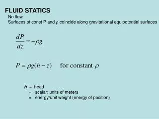
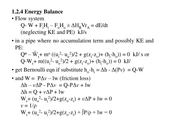
1.2.4 Energy Balance Flow system Q- W + F i H i – F o H o ± ΔH R Vr A = dE/dt (neglecting KE and PE) kJ/s in a pipe where no accumulation term and possibly KE and PE: Q o – Ŵ s + m o ((u i 2 - u o 2 )/2 + g(z i -z o )+ (h i -h o )) = 0 kJ/ s or

E N D
1.2.4 Energy Balance • Flow system • Q- W + FiHi – FoHo ± ΔHRVrA = dE/dt • (neglecting KE and PE) kJ/s • in a pipe where no accumulation term and possibly KE and PE: • Qo – Ŵs+ mo ((ui2- uo2)/2 + g(zi-zo)+ (hi-ho)) = 0 kJ/ s or • Q-Ws+ m((ui2- uo2)/2 + g(zi-zo)+ (hi-ho)) = 0 kJ/ • get Bernoulli eqn if substitute ho-hi = Δh - Δ(Pv) = Q-W • and W = PΔv – lw (friction loss) • Δh – vΔP - PΔv = Q-PΔv + lw • Δh = Q + vΔP + lw • Ws+ (uo2- ui2)/2+g(zo-zi) + vΔP + lw = 0 • v = 1/ρ • Ws+ (uo2- ui2)/2+g(zo-zi) + ∫P/ρ + lw = 0
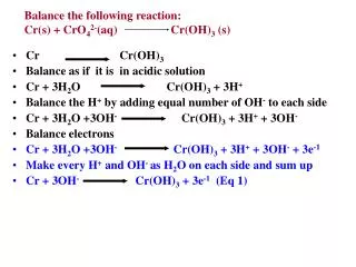
Typically in process flow calcs perform material balances followed by energy (as they are coupled) • Terms used in energy calcs: • Heat of reaction – ΔHr - enthalpy change when stoichiometric quantities of reactants at T and P are completely converted to products at same T and P • ΔHr < 0 reaction is exothermic e.g most fossil fuel combustion • ΔHr > 0 reaction endothermic e.g. most fossil fuel pyrolysis
1.3 Heat Exchange Equipment i. shell and tube
ii. Condensers • heat transfer equip used to liquefy vapours where latent heat of vap us absorbed w/ coolant • iii. Reboiler • usually shell/tube ex used to boil liquid for recirculation www.distillationgroup.com
iv. Cooling Towers • used to lower temp of recirc water used in condensers and heat exchangers • large diameter columns with special packing to give good contact with low P drop • water distributed thru tower via nozzles or troughs of pies and air passed thru forced draft and induced draft fans Closed Loop Cooling Tower System (www.cheresources.com)
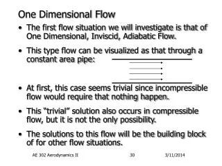
1.4 Mass transfer Ops • mass transfer processes can be modelled by diffusion rate processes (gas absorption, l-l extraction, packed towers) and/or equilibrium stages (distillation, leaching, extraction in distillation towers, diffusion batteries) • regardless of model need to know equilibrium relationship between phases and components because once 2 phases are in equilibrium there is no mass transfer • as said before equilibrium is set by T, P, n so use phase rule: F=C-P+2 determines degree of freedom for phase calcs • Eqm relationship • in our applications focus on distillation columns which are series of eqm stages • where two streams run counter-currently to each other, in each stage they are brought into contact, mixed, and separated, to work must enter stage not in eqm and leave very close to eqm • distillation or fractionation is a method of separation of HC by relative volatility • ij=Ki/Kj • where K- K-values = yi/xi really a measure of separation between liquid (x) and gas (y) fractions at a give T and P
fractionators • are designed as a series of equilibrium flashes: • equilibrium flash – say have a pure component of vapour and liquid at specified T and P, at equilibrium a certain fraction exists as vapour the rest as liquid, if change temp and/or pressure and allow to equilibrate fractions will shift, if now add other compounds to pure and allow to equilibrate the l and v fractions and composition will again shift how shift determined by thermo f(comp, T, P) v, y1 TS PS Tin, Pin, z1 TS Tin l, x1 y1 x1
in series of flashes: • vapour enters from stage below @ T1 • l enters from stage above @ T2 (T1>T2) • heat and mass transfer occurs so exit streams from stage @ bubble pt l and dew pt v at same T and P dew pt v l at T2 T2 Stage may be a tray or part of packing (discussed in detail later) T contact v at T1 bubble pt l T1 yDP xBP • composition of exit streams are related by equilibrium constant (K) • Ki = ydp/xbp where K=f(T,P) – calculate using thermodynamics (del G or chem potential)
Condenser – may have total or partial reflux Reflux Overhead Rectifying Section – v enriched w/ low boilers Stripping section – l enriched w/ high boilers Reboiler Figure modified from Perry’s Bottom Product
May have multiple feeds at low T as approach top to provide reflux • Use top l feed w/ crude stabilizers and deethanizers • purpose is usually meet specs for bottom product , OH composition determined by upstream process units • trayed • 1. bubble cap – prevents l from weeping thru vapour passages • -turndown ratio 8:1-10:1 • 2.valve – lower cost • 3.sieve or Perforated – lowest cost, high capacity but subject to weeping • initial design calcs based in theoretical trays (eqm calcs) and then apply a tray efficiency Bubble Sieve Valve
packed columns • as opposed to tray columns, contact btw l and v maintained throughout column (vs. specific pts) more detail later • number of trays function of separation factors where Hv is the enthalpy of the feed at the dew point, HF is the enthalpy of the feed at the boiling point, and HL is the enthalpy of the feed at its entrance condition • numbers 1-6 represent theoretical amount of trays required to achieve separation never truly reach eqm at trays therefore apply “tray efficiency” Typical McCabe-Thiele diagram for distillation of a binary feed (Perry’s)
condenser – partially or totally condense the vapour to a boiling liquid to return to column and enhance mass transfer as it is transferred to rising vapour stream called reflux (increases purity of OH product) • reboiler – liquid partially reboiled to vapour • temperature increases as move down column due increase in pressure and concentration of higher boiling components • in design mass and energy balances are done at each stage or plate to determine final concentration, T and P profiles.
Liquid/Gas Absorption ops • includes absorption, stripping and desorption • soluble vapour absorbed from mixture with a liquid (solute), solute is then regenerated can also have gas absorption with reaction (discuss later) absorber vs. fractionator
Packings/packed tower design • usually use a tower with packings or trays/valves to accomplish gas absorption cylindrical column (tower), with gas inlet, and distributor at the bottom, liquid inlet and distributor at top, gas and liquid outlets at top and bottom, and supported mass of inert packing or series of trays/valves • can be a “physical” absorption process occurs due to solubility and vapour-pressure relationships or, • chemical absorption chemical reactions between absorbed substance and the absorbing medium • packing increase the area of contact between gas and liquid this results in increased mass transfer between phases • the solute in the RICH gas is absorbed by the liquid and exits the tower as a LEAN gas
3 types of packing: • 1. dumped or random packing – units 6-75 mm in diameter, cheap inert material (clay, porcelain, plastics) • - area/volume column = 65-625 m2/m3 • 2. stacked – 50-200 mm in size, not commonly used due to channelling • 3. structured – knitted type mesh packing (i.e. wire gauze) • - high l loading possible • - area/volume column = 200-250 m2/m3 structured random stacked http://www.tower-packing.com/Dir_structured_packing.htm
initial design calcs based on P drop and diameter (Eckert method) • must minimize P drop across column (low gas mass velocity) which also prevents flooding (high l or v rates when delPgas > net gravity head of l) but if gas mass velocity too low then must have larger column to maximize contact between l and v • e.g. del Pmax=5-15 mm H2O/ft packed depth (max of 25) or • del Pflood = 0.115Fp0.7 • where Fp is packing factor (dimensionless, del P in H2O/ft pack) (l/v)max flooding operating range liquid flowrate stripping max delP rectifying channeling min allowable eff vapour flowrate
other column problems that must be mitigated by operating properly: • foaming • entrainment • weeping (when trays rely on gas pressure to hold l start leaking l thru gas orifices) • the maximum amount of solute that can be absorbed by the liquid is defined by equilibrium calcs, actual amount is less and called the operating line: Operating line - absorption Tower bottom Equilibrium line y Operating line - stripping Tower top x ** reversed op and eqm line for distillation
instead of efficiency have Height of Packing Equivalent to Theoretical Plates (or trays) HETP inversely prop to eff • then HETP*theoretical stages = hPC ~ 300-900 mm (1500 max) • critical to maintain l distribution (avoid channelling) so redistribute ~ every 6 m of packing or 10 column diameters • regenerate liquid in adjacent column
iii.) solid/gas absorption or fixed bed absorbers and fluidized beds • solid acts as absorbent to remove impurities • as with gas-liquid contactors can have physical or chemical absorption • adsorbent particles placed in bed 0.3-1.2 m deep supported on screen or perf plate, feed gas flows down thru bed to prevent fluidization, usually have 2nd bed regenerating • fluidized beds solid particles are fluidized to enhance mass and heat transfer