Download
1 / 36
360 likes | 472 Views
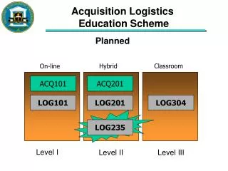
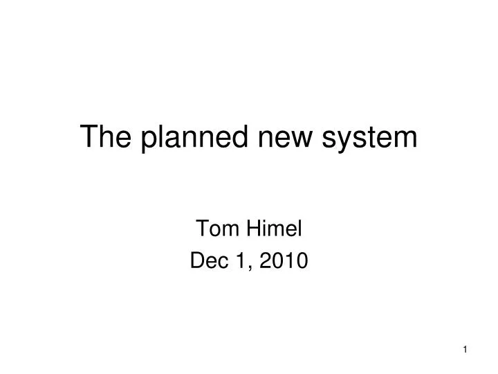
The planned new system. Tom Himel Dec 1, 2010. Outline. Controls has multiple related projects Decided to use mainly µTCA architecture Description of µTCA Advantages of µTCA Pros and Cons and our decision making process Summary. Controls has multiple related projects.

E N D
The planned new system Tom Himel Dec 1, 2010
Outline • Controls has multiple related projects • Decided to use mainly µTCA architecture • Description of µTCA • Advantages of µTCA • Pros and Cons and our decision making process • Summary
Controls has multiple related projects • Upgrade LLRF for 1 LCLS RF station • Funded for $1.8M from AIP • Requirements mostly done, design started • Upgrade 10 sectors (80 RF stations) of LLRF (could be 21-30 or 11-20) • Will be proposed when above prototype is finished at cost of ~$25k per station = $2M • Develop and industrialize the new µTCA standard and use it to instrument ILC 10 MW klystron - interlocks and feedbacks • Funded for $2M from ILC about 60% done • Standard nearly signed, companies producing shelves and modules
Controls has multiple related projects • “station node project” • Upgrade multiple systems near a single RF station: stripline BPM, toroid, vacuum, motion control?, temperatures? Profile monitors? • Proposed $2.8M AIP • This project is immediate cause of this review. • Upgrade sectors 11-20 • Will be proposed at cost of ~$10M when above prototype is done • Another ~8M needed for related non-controls upgrades: SSSB, magnet PS, modulator PLC • Build LCLS-II • Want to coordinate these projects to take advantage of synergies (sharing of module types and space in crates)
Why upgrade the linac? • If that isn’t obvious to you after the last talk, we have invited the wrong reviewers. • Want better reliability and maintainability • Want components for which we can get repair parts • Want mostly commercially available components
The architecture choice • We have spent considerable time and many group meetings deciding on the architecture to use. • Decided on µTCA • Will first describe µTCA to you • Then explain its advantages • Then share the pros and cons matrix that went into our decision making process
Genealogy of µTCA • ATCA (Advanced TeleCommunications Architecture) is a standard developed for the telecommunications industry. • Emphasis was on high availability and high bandwidth. • There are many commercial modules available • Modules are physically large (~fastbus size) • Connections to smaller daughter boards are part of the standard.
Genealogy of µTCA • These daughter boards are called AMC (Advanced Mezzanine Cards). • Several can be mounted on an ATCA carrier card. • Often the carrier card must be customized for the particular AMCs used to route in the necessary I/O from the cables that go to the RTM (Rear Transition Module) attached to the ATCA card. • Some small projects can be done with ONLY AMC cards.
Genealogy of µTCA • This led to first the µTCA standard and then to the µTCA for physics standard. • The physics standard is twice the size of the minimum sized µTCA (AMC) card and has a connector for an RTM. It is backplane compatible with a standard µTCA card and simply defines the use of some spare lines on the backplane. • It is the µTCA for physics we plan to use and it will hereafter be referred to simply as µTCA. • The µTCA standard was developed as an international industry/lab committee under the auspices of PICMG. • The standard is virtually complete, but final signatures are still awaited. • A small but growing number of commercial products are available.
µTCA features • IPMI: Standard out-of-band network to monitor temperatures, fan speeds, voltages of both crates and modules. Allows remote control of power to individual modules. Standard software available to implement all of this. • Redundant hot-swappable fans allowing this most commonly failing component to be replaced without program interruption • Ability to have redundant power supplies and network hubs • Timing distribution provided on backplane
µTCA features • Truly hot swappable modules and RTMs. • Allows bad modules to be swapped without added degradation of the control system. • This in turn allows more modules to be in a crate and hence fewer crates without degrading system availability. • Split between AMC and RTM allows an AMC module to be used for several purposes by having different relatively simple RTM cards. E.g put the ADC on the AMC module and have RTM cards with different signal shaping for BPMs and toroids. • Uses point-to-point communications instead of busses. Allows for high bandwidth and avoids subtle bus problems where a problem in one module causes problems in another. • Low noise environment suitable for analog electronics. • Solid, well tested mechanical and connector designs
Keying User I/O PowerSystem Mgmt AMC µRTM Standard AMC Connector and Backplane AMC & µRTM Modules – µTCA.4
Industry Prototypes:6-Payload Shelf µRTM • Development Shelf 6-Slot • Physics Backplane • Non-Redundant MCH, Fans, Power Module µRTM
µTCA.4 Development Platform • SLAC Linac controls upgrade • 6-Slot Prototype Shelf w/ MCH, Processor, Interim Timing System, power module, built-in fans • PMC Event Receiver (EVR) on double µTCA Adapter • Shelf non-redundant • All rear I/O access
12-Payload Shelf • Full µTCA.4 Compatibility • Fully redundant MCH, power, fans
DESY XFEL will use µTCA in the tunnel Courtesy K. Rehlich DESY
Prototype for XFEL. We have one. • + 2 16 bit DACS
Slow I/O can be done with IP cards There is also a PMC carrier that we presently use for our timing card
µTCA summary • Scaleable modern architecture • From 5 slot μTCA …full mesh ATCA • Gbit serial communication links • High speed and no single point of failure • Standard PCIe, Ethernet communication • PCIe and Ethernet is part of Operating System • Redundant system option • Up to 99.999% availability • Well defined management • A must for large systems and for high availability • Hot-swap • Safe against hardware damage and software crashes
Our Architecture decision • We briefly looked at many standards • Carefully compared network attached devices (rack mounted chassis with Ethernet ports), VME and µTCA. • We expect to end up with a mixed system, so really deciding what standard to use for new and improved things.
Why not simply clone what we just did for LCLS-I • Some parts not done at all (linac LLRF) • Unhappy with other parts (stripline BPM) – more later • We likely will clone some of the parts like PLC system for vacuum and perhaps Beckhoff for temperatures and misc I/O
LCLS BPM rack Front Rear
BPM chassis • Each has: • 4 signal cables (unavoidable) • A trigger at beam time cable • A calibration trigger cable • An ethernet port for channel access • An ethernet port used to pass raw data at 120 Hz to a VME IOC for processing as the internal CPU is too slow • A serial connection to a terminal server to allow viewing of the IOC console • A power cable to an ethernet controlled power strip so power can be cycled to perform a remote reset.
BPM chassis • This was a design kludged together from available parts in 4 months when originally planned design for LCLS failed. • Was then propagated to 10 linac sectors as didn’t have time to do a proper redesign and wanted its improved analog performance. • It works! Physicists are quite happy. But REALLY don’t want to propagate this again! Needs a design using a crate e.g. µTCA.
BPM in µTCA • Each module has: • 4 signal cables (unavoidable) • A trigger at beam time cable • A calibration trigger cable • An ethernet port for channel access • An ethernet port used to pass raw data at 120 Hz to a VME IOC for processing as the internal CPU is too slow • A serial connection to a terminal server to allow viewing of the IOC console • A power cable to an ethernet controlled power strip so power can be cycled to perform a remote reset. On backplane On backplane PCIe on backplane to CPU PCIe on backplane to CPU Only CPU has one IPMI handles this
VME situation • VME is almost 30 years old: our system should operate for another 20-30 years. • Number of new developments is decreasing, sales are still constant • Bus technology has speed limitations • Wide busses create a lot of noise in analog channels • No standard management on crate level • No management on module level • So far no extension bus survived • One damaged bus line stops a whole crate • Address and interrupt misconfigurations are hard to find
Reasons for choosing µTCA • Use an industry standard to share with others • Redundant fans and hot swappable fans and modules allows for troubleshooting and maintenance during user runs and improving reliability • Cable plant reduction compared to network attached devices • Systems can share crates with minimal impact
Reasons for choosing µTCA • Firmware can be remotely loaded (presently we bring each module to the lab for this) • Standard system to monitor temperatures and voltages • A new standard rather than one nearing retirement • Modular so pieces of it can be upgraded • Allows use of new technology that allows us to challenge and keep good engineers.
Decision spreadsheet • The presentation so far has been one-sided, listing the advantages of µTCA and no disadvantages. • We were much more balanced in our decision making process. • The spreadsheet at the same site as this talk contains the detailed pros and cons list that was a key part of our decision making process. https://slacspace.slac.stanford.edu/sites/reviews/ad/linaccontrol_dec_2010/Pages/default.aspx
A few design details • Having made the major architectural decision, there are still many design decisions to be made. • We have a proposed AIP project which is mostly R&D where most of those decision will be made. • This review doesn’t really have time to go into design details anyway, but I’ll list some of the next level decisions we have made.
A few design details • We will have 1 µTCA shelf near each klystron that will have the LLRF, 0-3 BPMs and whatever else needs handling that is nearby. • It will be a 12 slot shelf. • There will be an air to water heat exchanger in the rack with air that circulates through it and the crate. • We will reuse the current racks but bring them up to today’s standards
A few design details • We are working with Struck and Vadatech to modify existing ADC designs they have to meet our requirements for LLRF and BPM • We expect all our AMCs to be commercial but we will design a variety of RTMs • There will be some rack mounted chassis to handle large cable plants, high power or high voltage. • We have a list of all our systems and how we plan to handle them. Some plans are tentative depending on availability of resources.
Summary • The linac control system clearly needs upgrading • It would be missed opportunity to not do it during FACET era with runs of only 4 months per year • µTCA is the best choice for the architecture • We should get started as there is a lot of work to do. • If we go fast enough, most of the LCLS-II upgrade can also be done with µTCA