Download
1 / 24
240 likes | 353 Views
ISRM project DFBXs Splice measurements Richard Mompo on behalf of ELQA team. ISRM on DFBXs. There are 8 DFBXs in the LHC. 4 of them have an additional D1 magnet connected . 2 measuring set- up were prepared in order to measure 2 DFBXs at a time

E N D
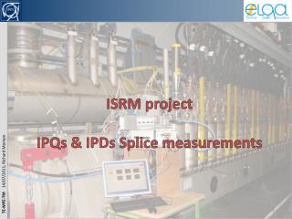
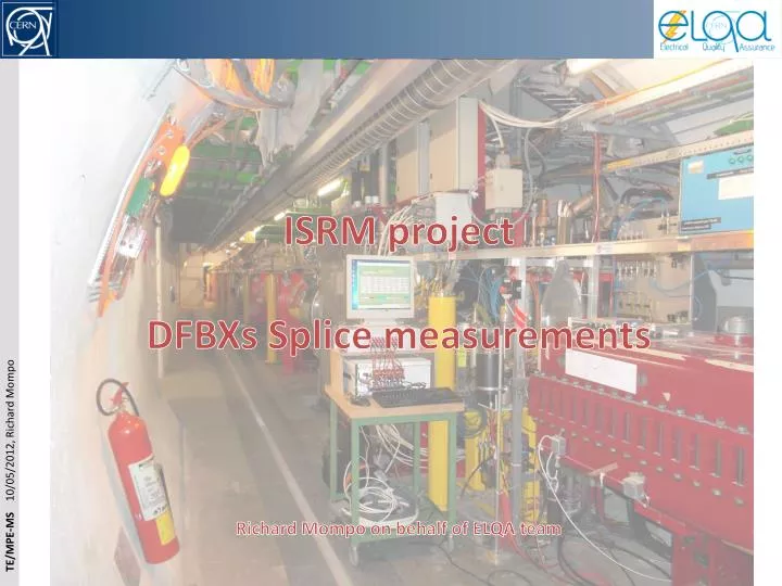
ISRM project DFBXs Splice measurements Richard Mompo on behalf of ELQA team
ISRM on DFBXs • There are 8 DFBXs in the LHC. • 4 of them have an additional D1 magnet connected. • 2 measuring set-upwere prepared in order to measure 2 DFBXs at a time • The measurements took place at the end of the Xmas break during the powering phase. • The DAQ was based on a PXI crate equipped with 7 or 9 high precision DVMs. • Same principle as already applied for ISRM on IPDs, IPQs with QPM software. • We measured each DFBXs from the tunnel side. • To avoid long cables and because of availability of additional diagnostic connectors (that are not routed to QPS controllers which are standing in the UAs/Ujs). • Circuits RQX/RTQX2 were powered together with a Mexican pyramid. • Use of standard power cycle “PNO.D11” with 3 current plateaus reduced to 10 min. each (instead of 1h). • D1 magnets were measured separately. • Use of standard cycle power “PNO.c2”
DFBX Layout in LHC During PNO.D11, RTQX1 power converter is OFF.
Current plateaus for each DFBX DFBX in R1: Current levels for are much lower? Why?
PNO.D11 cycle with voltage measurements Q2 is seeing 9700 Amps!
D1 splices belong to another family and should be compared to other IPDs
We have more noise on DVM 1, 4, 5 and 7! Probably because we are mixing a current lead voltage tap with a magnet voltage tap Means there are not routed the same way up to the DFBX
I made the assumption that all splices are identical! DVM3 and DVM7 of DFBXB.R1 are slightly outside of the Gaussian curve
Conclusions • We managed to measure all 8 DFBXs during 2011-2012 Xmas break. • We did not measure all Q1, Q2a, Q2b and Q3 internalsplices (splices between poles)! • From a statistic point of view, it looks like the nominal resistance value for the 2 groups of splices are: • Around 0.5 E-09 Ohms for Q1, Q2 and Q3 splices • Around 1 E-09 Ohms for D1 splices (comparable with other IPDs magnets) . • All splices measured are below 5 E-09 Ohms so there is nothing worrying! • An internal note will follow similar to the one written for IPDs and IPQs: • EDMS 1172291
Spare slides Technical drawings